G
Guest
Guest
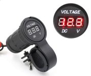
picked up one of the earthquake proof ones. Does this wire right to the battery? maybe i could wire it into my sspb?
Required reading for all forum users!!!
Welcome!
Register to access the full functionality of the GSResources forum. Until you register and activate your account you will not have full forum access, nor will you be able to post or reply to messages.
A note to new registrants...
All new forum registrations must be activated via email before you have full access to the forum.
A Special Note about Email accounts!
DO NOT SIGN UP USING hotmail, outlook, gmx, sbcglobal, att, bellsouth or email.com. They delete our forum signup emails.
A note to old forum members...
I receive numerous requests from people who can no longer log in because their accounts were deleted. As mentioned in the forum FAQ, user accounts are deleted if you haven't logged in for the past 6 months. If you can't log in, then create a new forum account. If you don't get an error message, then check your email account for an activation message. If you get a message stating that the email address is already in use, then your account still exists so follow the instructions in the forum FAQ for resetting your password.
Have you forgotten your password or have a new email address? Then read the forum FAQ for details on how to reset it.
Any email requests for "can't log in anymore" problems or "lost my password" problems will be deleted. Read the forum FAQ and follow the instructions there - that's what we have one for...
If you are a returning visitor who never received your confirmation email, then odds are your email provider is blockinig emails from our server. The only thing that can be done to get around this is you will have to try creating another forum account using an email address from another domain.
If you are a returning visitor to the forum and can't log in using your old forum name and password but used to be able to then chances are your account is deleted. Purges of the databases are done regularly. You will have to create a new forum account and you should be all set.
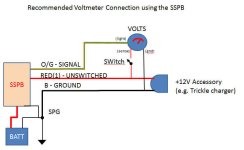
Hook it to O/G (Pin7) SIGNAL or the RED2( Pin 8) switched ACCESSORY if you want the voltmeter only ON when the ignition switch is on. You would need t o jumper ACCESSORY to come on with the IGNITION SW however. If you use O/G, then keep it as close to the SSPB output as possible. If you converted to Led then probably any where on o/g.picked up one of the earthquake proof ones. Does this wire right to the battery? maybe i could wire it into my sspb?

Wow. I think I got that right! Except for tapping into the Gr wire (tach, speedo, etc. lights) in the headlight bucket for gauge power. Why keep it as close as possible to SSPB on the O/G? I figured that wouldn't matter, as long as the sense wire was as close as possible to the battery, and Neg at SPG.
Thanks for the amazingly helpful info (yet again).
Grey is the O/G just down stream.
The sense wire (you still not running a SERIES R/R?) keeps the R/R charging the battery at the proper 14.5V even if there is resistance between the Battery(+) and the R/R(+). It doesn't help for dirty grounds). However if you are drawing 5-10 amps for blinker, brakes and tail light through the O/G and there are dirty contacts you could get quite a big drop when you consider you are trying to monitor the battery voltage.
If you take O/G output right at the SSPB then the only voltage drop is due to the SSPB MOSFETS which is about 0.1 ohms.
On the other hand if you did not load the SWITCHED accessory and used that as your sense point, it would basically be extremely close to battery voltage as you are not pulling any current from it.
Basically for measuring voltage you need to be as close to the battery as you mentioned, but you need it switched and the SSPB is in fact a bunch of electronics switches. So the closest thing to the battery that is switched is the output O/G of the SSPB.
Note the 0.1 ohm resistance is slightly more than a perfectly clean contacts or mechanical relay. However, those things do not stay pristine and will corrode increasing the resistance. On the other hand the MOSFET does not degrade and doesn't get any worse.
Given all that teh O/G may not even be teh best choice.
Pos, what you're describing doesn't sound like the schematic you drew. Or at least, my reading of it. My distal connection to O/G powers the gauges ("lights" on your schematic). The voltmeter's positive wire ("sense") is almost directly on the battery terminal, so I don't have a collection of voltage drops on it. The gauge reads almost exactly the same voltage my multimeter reads at the battery terminals.
My regulator has been a Cycle Electric 601 for four years now. I was referring to the new voltmeter's sense wire, not a 5- or 6-wire R/R.
I described several things that I figured did not need a diagram.So you are correct the diagram does not reflect connecting the voltmeter to O/G or RED2 the two things I initially mentioned. As you see above, O/G and RED2 are only recommended if you DO NOT want to measure the voltage when the bike was off.Hook it to O/G (Pin7) SIGNAL or the RED2( Pin 8) switched ACCESSORY if you want the voltmeter only ON when the ignition switch is on.
I described several things that I figured did not need a diagram.So you are correct the diagram does not reflect connecting the voltmeter to O/G or RED2 the two things I initially mentioned. As you see above, O/G and RED2 are only recommended if you DO NOT want to measure the voltage when the bike was off.
However, the diagram is how I would suggest using the SSPB for use for a power plug and to monitor the voltage as I can do it with the bike off. I figured this did need diagram to show those details.
OK, that all makes sense to me. But the way I read your post, it sounded like you expect the voltmeter to measure voltage from O/G, instead of from the wire labeled "sense" on the schematic.
37mm diameter digital oil temp gauge to match the voltmeter... not too sure about how weatherproof it might be, or how easily it could be made so, but it's cheap enough to find out. I'm sure I can find a bar mount clamp from one of the many sellers of flashlight mounts for bicycles.
http://www.aliexpress.com/store/pro...ure-Gauge-Meter-Silver/412191_1532796275.html
The seller has a range of other instruments.
These are not waterproofed like the expensive $5 units. But for $2.68 how can you go wrong?
http://www.ebay.com/itm/DC-3-50-30-...7&pid=100005&rk=3&rkt=6&sd=301611670229&rt=nc
The high end model............
http://www.ebay.com/itm/Waterproof-...7&pid=100005&rk=2&rkt=6&sd=301611670229&rt=nc


 Another $1.50 down the drain.