U will see the process for different combinations here.
http://www.thegsresources.com/_forum/showpost.php?p=1026173&postcount=23
http://www.thegsresources.com/_forum/showpost.php?p=1026173&postcount=23
Required reading for all forum users!!!
Welcome!
Register to access the full functionality of the GSResources forum. Until you register and activate your account you will not have full forum access, nor will you be able to post or reply to messages.
A note to new registrants...
All new forum registrations must be activated via email before you have full access to the forum.
A Special Note about Email accounts!
DO NOT SIGN UP USING hotmail, outlook, gmx, sbcglobal, att, bellsouth or email.com. They delete our forum signup emails.
A note to old forum members...
I receive numerous requests from people who can no longer log in because their accounts were deleted. As mentioned in the forum FAQ, user accounts are deleted if you haven't logged in for the past 6 months. If you can't log in, then create a new forum account. If you don't get an error message, then check your email account for an activation message. If you get a message stating that the email address is already in use, then your account still exists so follow the instructions in the forum FAQ for resetting your password.
Have you forgotten your password or have a new email address? Then read the forum FAQ for details on how to reset it.
Any email requests for "can't log in anymore" problems or "lost my password" problems will be deleted. Read the forum FAQ and follow the instructions there - that's what we have one for...
If you are a returning visitor who never received your confirmation email, then odds are your email provider is blockinig emails from our server. The only thing that can be done to get around this is you will have to try creating another forum account using an email address from another domain.
If you are a returning visitor to the forum and can't log in using your old forum name and password but used to be able to then chances are your account is deleted. Purges of the databases are done regularly. You will have to create a new forum account and you should be all set.
On those Koso instructions there is a big note stating to make sure the Tach signal comes from coil + otherwise the meter could break....
I thought the Orange White was coil +? Am I wrong??
On those Koso instructions there is a big note stating to make sure the Tach signal comes from coil + otherwise the meter could break....
I thought the Orange White was coil +? Am I wrong??

")
Got through to Tech support today. Pierre - French Canadian by the sounds of it but good English.
He advised me that I should just connect up to that B/Y wire for the original stock Tach & select the "Hi" rating along with 4 cycle, 4 cylinder.
He said that the internal protection inside the gauge is pretty good & that I won't break anything if this doesn't work so I'll try to get it wired in & tested this week.
Dan
 .
.
") :lol:
:lol:Seems relevant to me...
Thanks
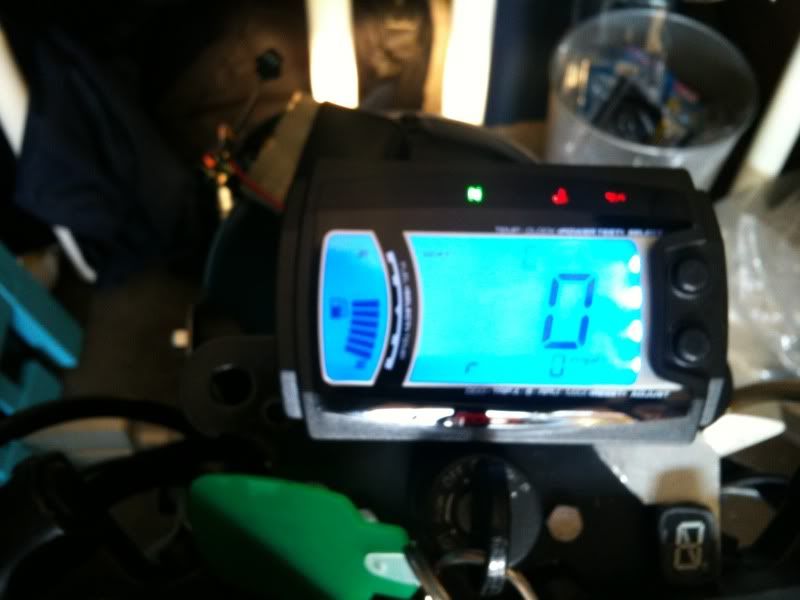
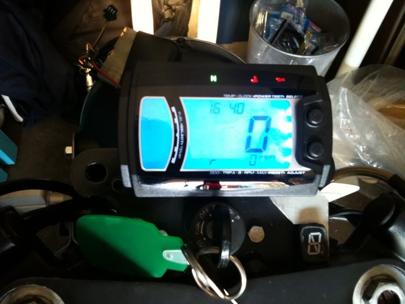
Will post pics etc when I have it set up - I may even make a video to keep Jim happy but I think the fancy music might be above & beyond for me