-
Required reading for all forum users!!!
Welcome!
Register to access the full functionality of the GSResources forum. Until you register and activate your account you will not have full forum access, nor will you be able to post or reply to messages.A note to new registrants...
All new forum registrations must be activated via email before you have full access to the forum.A Special Note about Email accounts!
DO NOT SIGN UP USING hotmail, outlook, gmx, sbcglobal, att, bellsouth or email.com. They delete our forum signup emails.A note to old forum members...
I receive numerous requests from people who can no longer log in because their accounts were deleted. As mentioned in the forum FAQ, user accounts are deleted if you haven't logged in for the past 6 months. If you can't log in, then create a new forum account. If you don't get an error message, then check your email account for an activation message. If you get a message stating that the email address is already in use, then your account still exists so follow the instructions in the forum FAQ for resetting your password.Have you forgotten your password or have a new email address? Then read the forum FAQ for details on how to reset it.
Any email requests for "can't log in anymore" problems or "lost my password" problems will be deleted. Read the forum FAQ and follow the instructions there - that's what we have one for...
-
Returning Visitors
If you are a returning visitor who never received your confirmation email, then odds are your email provider is blockinig emails from our server. The only thing that can be done to get around this is you will have to try creating another forum account using an email address from another domain.
If you are a returning visitor to the forum and can't log in using your old forum name and password but used to be able to then chances are your account is deleted. Purges of the databases are done regularly. You will have to create a new forum account and you should be all set.
You should upgrade or use an alternative browser.
GS(X)1100E turbo EFI
- Thread starter ArttuH
- Start date

madjack57754
Guest


The can will be cut shorter when I install inner parts in it. The passenger pegs are real PITA when building the exhaust. It's just impossible to place the can so that it looks good and gives enough ground clearance.
Water injection components will need more space so I built new fender that gives more space under the seat.


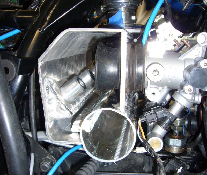
Place the stubs on the throttle bodies and tack them on the plenum front wall. Check that they are still in correct position. Looks good.

Clamp the assembly on the table to prevent distortion and weld the stubs properly. (I'm still learning alu welding.) Ok, it stayed pretty straight but the flange gained a couple of millimeters length. So no hope to fit it on the TBs anymore :evil:

Then some desperate fixing attempts and melt one of the stubs to unusable condition. Game over!

So I decided to take new angle of attack on this. I realized that I have the GSXR air box rubber boots that actually look quite handy. So let's see what I can do with them.

Looks pretty good except length difference. So I have to get another set of these rubber boots to get equal length set. Only question is if the boots will stay on their place under the boost but I'm quite confident. They fit in the holes quite firmly.
Internal parts:
And finished item:
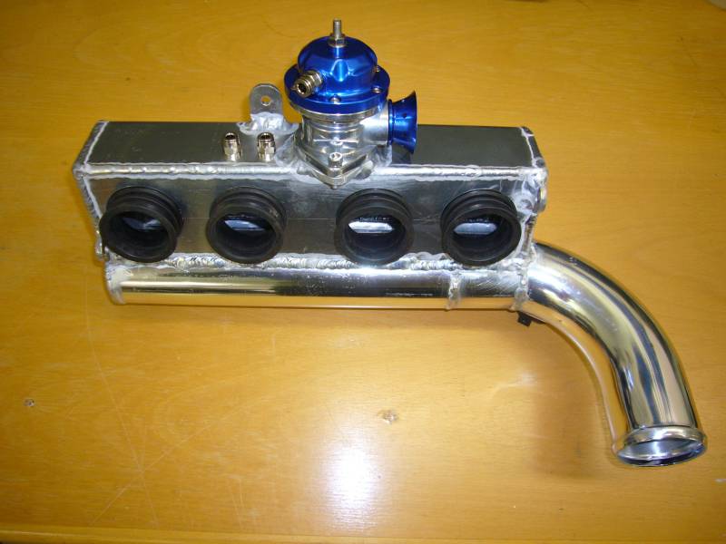
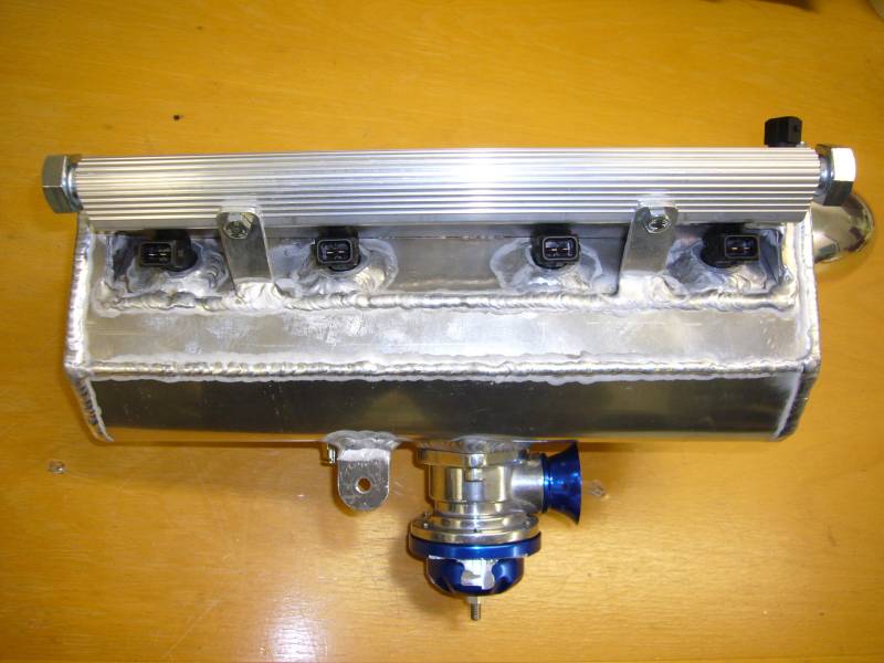
Now I just have to decide if I will polish it or just paint it black. Right now I'm leaning towards painting. After spending several hours by scrubbing exhaust pipes trying to make them look decent I got a strong feeling that polishing is pretty pointless work
")
Anyway, the exhaust is also ready except the end can bracket.

Good stuff
Well done Arttu. That plenum chamber looks well designed. It should provide even boost over each cylinder. If they're a good tight fit, those rubber velocity stacks should seal ok with the boost levels you'll be using.
Ali's a very challenging metal to weld. It's real easy to input too much heat on thinner sections. Painting it black will probably assist with heat dissipation too.
Hope it runs as good as it looks.
Ali's a very challenging metal to weld. It's real easy to input too much heat on thinner sections. Painting it black will probably assist with heat dissipation too.
Yep, that's true. I should learn to use foot pedal with my TIG, it would be handy in many cases. But first I have to modify the pedal slightly. Currently it's adjusting current from zero to 300A so it's virtually useless. I'm going to add pots to adjust min and max currents, then it should be fine.
Not sure about heat dissipation with black paint. Keeping in mind that there is a hot engine next to the plenum it will probably absorb more heat than dissipate.
Let's hope soHope it runs as good as it looks.
Guest
Guest
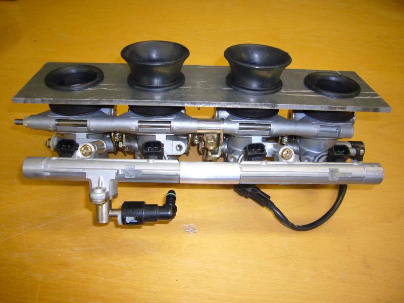
TB's
Hello Arttu
What did you do/use to plug the secondary shaft holes in the TB's? Epoxy or weld? Or?
Tanx
G
I needed more space inside the rear cowling for water injection tank so I converted the tail light into LED version.

The result is much slimmer and in addition I got brighter brake light with less than half current draw.
Original one on the left and LED version on the right.

Then there was enough space for water tank. 1.5 liters, I guess it's enough for almost anything.

And mock up on the bike. The water pump found it's place as well.

I guess that larger oil cooler wouldn't be a bad idea. So I mounted a 13 row Mocal cooler, should be enough, I think. Initially I planned to route oil through water passages of the turbo but plumbing for that was looking desperate so I gave up the idea.


I also decided to open up the crankcase mouths while the engine is in pieces. Just in case if I go crazy some day and want some big block


I bet that run out figure is better than most achieve after welding those cranks, even the Suzuki factory jobs!!
Yep, factory spec is less than 0.1mm and I have heard that many factory cranks actually doesn't meet this spec.

As you can see there are two differences. At first the HD bearing doesn't have snap ring groove. This isn't very critical since these bearings shouldn't get any side load. Another thing is missing dust seal that the original one has. At first I thought that it doesn't make any practical difference but then I realized that this is actually pretty important thing. Pressure oil feed to the gears and clutch goes through ends of the shaft and these dust seals are necessary to prevent oil to escape straight through the bearings. So with these HD bearings the gears and clutch wouldn't get any pressure lubrication!
I'm not sure how tragic this would be in practice. I guess that this might be ok in drag use where the transmission doesn't see too many revolutions between engine rebuilds but I wouldn't try my luck with street engine that is supposed to see plenty of road.
Fortunately these were just standard bearings so it was easy to get ones with snap ring groove and dust seal from local engineering shop. I'm just wondering why they didn't put correct bearings in the kit at the first place

The APE head studs and main bearing studs installed.

Transmission got undercut for second and third gears.

Cases vent together nicely, all shafts are still spinning and even the gears seem to work.
Assembling the clutch.

Pressure plate with steel buttons for lock-up. Thanks for Blower1!

I adjusted compression ratio by machining dishes on piston tops. The result should be about 9.1:1. Minimum crown thickness with dishes is a bit over 5mm, I hope it's enough. I also got ceramic coating on piston tops. Interesting to see if it lasts or give any noticeable benefit


I checked ring end gaps and adjusted them to slightly larger. I also weighted the pistons and found about 1 gram maximum difference between them. Almost started to remove material from heaviest pistons but then I weighted the wrist pins too and found out that they were varying by 0.5 grams. So proper mix resulted about 0.5 gram maximum variation for piston + pin combinations. Good enough, I think


The head required less work than I initially thought since the valve guides were all good. Just to be safe I decided to get new exhaust valves so they are now 1 mm oversized (24 mm) stainless ones. Along the seat work the head got light porting too. Meaning that porting was limited to valve seat area. This resulted about 10% increase in flow bench figures.
After installing the head with Cometic steel gasket I timed the cams to 106? in. and 110? ex.

And then top end.
I adjusted compression ratio by machining dishes on piston tops. The result should be about 9.1:1. Minimum crown thickness with dishes is a bit over 5mm, I hope it's enough. I also got ceramic coating on piston tops. Interesting to see if it lasts or give any noticeable benefit
I checked ring end gaps and adjusted them to slightly larger. I also weighted the pistons and found about 1 gram maximum difference between them. Almost started to remove material from heaviest pistons but then I weighted the wrist pins too and found out that they were varying by 0.5 grams. So proper mix resulted about 0.5 gram maximum variation for piston + pin combinations. Good enough, I think
Great pics Arttu. You should be OK with 5mm crown thickness. You're not boosting over 1.5 bar are you?
Your piston/pin weight combinations should be good at 0.5 grams variation.
I see your piston weighs around 216 grams. I got my 850's down to 198 grams . The crowns are just 3 mm thick while running 10.5 -1. I reasoned that they would be strong enough because of the high domed shape. I didn't install the JE pins as they were quite heavy (could have run diesel compressions with them), so I bought new stock 850 pins and ground their lengths back 1.5mm to match the JE gudgeon bosses. Saved some weight using the modified stock pins as well.
Did you check all the sealing surfaces on your Cometic Steel head gasket. Some GSR 1100/1150 engine re-builders have had unhappy experiences with oil spewing from their engines, after fitting MLS gaskets.
The different transmission bearing designs could account for early bearing failures as you have pointed out. I'd be sticking with the originals with shields and the snap ring locating grooves too.