• Required reading for all forum users!!!

    Welcome!
    Register to access the full functionality of the GSResources forum. Until you register and activate your account you will not have full forum access, nor will you be able to post or reply to messages.

    A note to new registrants...
    All new forum registrations must be activated via email before you have full access to the forum.

    A Special Note about Email accounts!
    DO NOT SIGN UP USING hotmail, outlook, gmx, sbcglobal, att, bellsouth or email.com. They delete our forum signup emails.

    A note to old forum members...
    I receive numerous requests from people who can no longer log in because their accounts were deleted. As mentioned in the forum FAQ, user accounts are deleted if you haven't logged in for the past 6 months. If you can't log in, then create a new forum account. If you don't get an error message, then check your email account for an activation message. If you get a message stating that the email address is already in use, then your account still exists so follow the instructions in the forum FAQ for resetting your password.

    Have you forgotten your password or have a new email address? Then read the forum FAQ for details on how to reset it.

    Any email requests for "can't log in anymore" problems or "lost my password" problems will be deleted. Read the forum FAQ and follow the instructions there - that's what we have one for...

  • Returning Visitors

    If you are a returning visitor who never received your confirmation email, then odds are your email provider is blockinig emails from our server. The only thing that can be done to get around this is you will have to try creating another forum account using an email address from another domain.

    If you are a returning visitor to the forum and can't log in using your old forum name and password but used to be able to then chances are your account is deleted. Purges of the databases are done regularly. You will have to create a new forum account and you should be all set.

M-Unit Blue on the 1982 GS750

LarsKroghStea

Forum Mentor
Hi, I have a build thread somewhere else on the forum:

https://www.thegsresources.com/_for...981-gs750-(gs750e)-Retro-Racer-project/page12

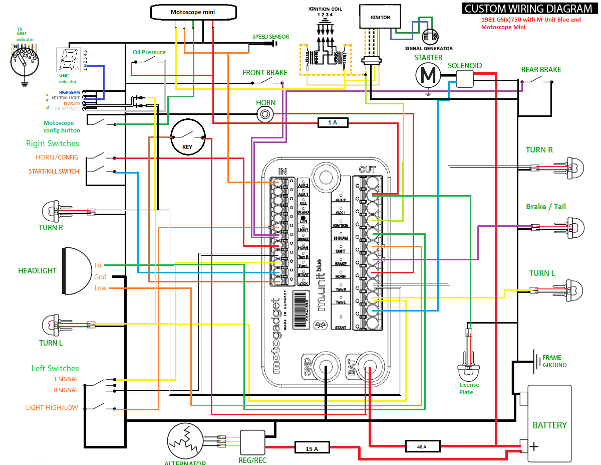
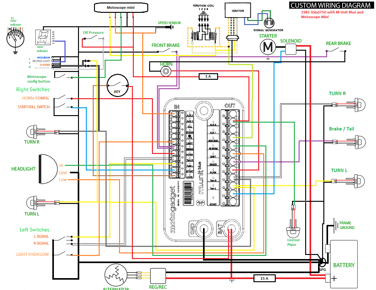
I'm currently working on the electrical system, and I'm not sure where to connect the regulator. Would it be best to connect it to the battery or to switched 12v on the M-Unit?

Here's my wiring diagram. I would love it if someone with knowledge of the gs electrical system would take som time to see if there are any major errors. (Except for the missing wire for the high beam indicator that i just spotted ;) ) Noisemaker_koblingsskjema by Lars Krogh-Stea, on Flickr
 
And here is the wiring for the motoscope mini:

instrumenten-montage-04-en.jpg
 

Attachments

  • instrumenten-montage-04-en.jpg
    instrumenten-montage-04-en.jpg
    15.4 KB · Views: 0
I know that "M-Unit" exists and have seen one in operation, but have NO idea what it takes to wire one up.

First of all, congratulations on the artwork. :clap: :clap: :encouragement:

It takes a LOT of effort to do a wiring diagram, yours is quite good. It took a while to see what was going on, due to the non-standard colors, but it appears that connecting the R/R output to the battery will be the best option, in your case.

.
 
The questions mark is contemplating the "T". That is exactly correct and the equivalent of how the SSPB is designed.

Note that you need at least 14 AWG on the two wires (Red and Black) from the R/R. The M-unit does not actually carry any ground currents, just enough for the internal electronics. On the other hand, the R/R black handles all return currents.

And yes, very nice schematics. :)


One nit is that you don't have an SPG indicated, but that may be an artifact of your schematic cannot be taken literally?
 
Last edited:
Thanks for the feedback :) The reason for the non standard colors is that I've used the colors for the Motogadget wiring loom. Makes it easier down the road I think.

Regarding single point ground, I thought you could do that through the frame. I was planning to ground the handlebar equipment in the front of the frame. If that is no good I'll just run a thicker wire from the battery to the front :)
 
This is the wiring diagram for a 750T? I'm having issues with my blinkers (turn indicators). I think the connections need to be cleaned...but geeze! That's a nice diagram!


Ed
 
Thanks for the feedback :) The reason for the non standard colors is that I've used the colors for the Motogadget wiring loom. Makes it easier down the road I think.

Regarding single point ground, I thought you could do that through the frame. I was planning to ground the handlebar equipment in the front of the frame. If that is no good I'll just run a thicker wire from the battery to the front :)

We I went from mildly concerned to headshaking concerned. Unless you follow the SPG guidelines, you will probably have recurring charging problems.
The "T" and the SPG are duals. One at the high side and one at the low side.
 
This is the wiring diagram for a 750T? I'm having issues with my blinkers (turn indicators). I think the connections need to be cleaned...but geeze! That's a nice diagram!


Ed
Yes, that is for a 750, but it is VERY different, due to the use of the M-Unit. :-k

The M-Unit Blue by Motogadget, replaces the fusebox. It also has built-in relays and circuit protection and offers many other things. Personally, I think it is a rather expensive answer to a problem that usually does not exist on our bikes. The one that I saw in use was on a bike that was acquired with a rather butchered wiring harness. Rather than fix or replace the stock harness, the current owner decided to strip it all out and replace it with an M-Unit (basic) and had a bunch of "fun" in the process. I helped him with some of his questions about how different thing functioned so he could program the M-Unit accordingly For all the effort that he went through (and much more, I'm sure, than I am aware of), he could have fixed the stock harness.

The diagram presented here is rather different than stock. If you notice, things like the oil warning light, horns and ALL of the lights are driven by the M-Unit. That part< alone, makes me nervous. You have to program the M-Unit to tell it whether the inputs are "active HIGH" or "active LOW". You also have to program the outputs to say whether they are "active HIGH" or "active LOW".

Oh, and besides all this effort, it's also not cheap. :-\\\

.
 
I noticed something else. You only indicated two stator legs?

On your grounding scheme, you have to complete the circuits (see picture below). I would not try and ground the handlebar switches through the handlebar. Run a single ground back to the SPG for the handlebar and a single ground run for everything else back to the SPG. If you harness naturally groups into 3 sections then do 3 direct runs to the SPG.


attachment.php
 
Last edited:
Thanks guys, your feedback is invaluable:) I can see now that the oil pressure light is drawn wrong. It is grounded in both ends :/ One leg is of course going to switched plus. The Aux2 output on the m-unit gives 12v whenever the ignition is on. This is equivalent to having it connected to the ignition switch (if you trust the m-unit, wich you should, in the same way you trust the digital components in your new car). The reason why I've done it this way is that there are two ways of turning on the ignition. With the key is the backup method, the normal way is approaching the vehicle with a Bluetooth enabled smartphone. When you do that, no key is needed.
I didn't buy the m-unit to fix any problems with the bike, as I could have just done the light switch charging mod. The rest was working fine. I did it because I wanted to replace the handlebar switches with microbuttons and I wanted the extra functionality like better light control, keyless go, programmable alarm, GPS trip logging easily transferred to smartphone, self resetting fuses, logging of voltage and currents for all outputs and logging of running time. You can also expand with wireless Bluetooth connected tyre valves for monitoring of tyre pressure if you want. Some think it's wrong to do these kind of modifications to an old bike, but as you can see in my thread this is hardly an original bike anymore. And I've already taken care of other safety issues like upgrading brake master to Accossato radials and installed new brakelines. Regarding the missing wire from the stator that is another diagram error. I copied the stator and r/r from another picture and one wire was missing. I'll do some modifications later on and post the new diagram. Once again; thank you :)
 
Last edited:
I've made a new diagram with the 15 amp fuse for the charging circuit and some other modifications. All ground is now leading back to the battery via wires, the oil pressure wiring is corrected and the alternator has three wires. I'll probably modify the routing for the ground wires when I lay it out on the bike.

Noisemaker_koblingsskjema by Lars Krogh-Stea, on Flickr
 
Good luck ...........

For everyone else I would strongly suggest NOT wiring the interconnect between the battery, R/R and M-Unit this way. It is critical to getting the power and ground distributions correct so that the system will age gracefully when corrosion sets it.
 
Last edited:
Good luck ...........

For everyone else I would strongly suggest NOT wiring the interconnect between the battery, R/R and M-Unit this way. It is critical to getting the power and ground distributions correct so that the system will age gracefully when corrosion sets it.

As I am fom Norway and English is not my native language I have to ask so there is no misunderstanding here.. Earlier you were talkin about the "T", what did you mean? By interconnect, do you mean the ground wire? And do you simply mean that it should be separate 12v and ground wires to the R/R?

I really want to do this the best way..

Sorry, if I was jumping the gun, but you seemed to be ignoring the posts, which I still think is true.
If you look at the links in my signature, you will find this one(below). There is a drawing that shows quite specifically how to connect the R/R battery and load. If it doesn't make sense, reread my prior comments. It is in reference to this diagram.

https://www.thegsresources.com/_for...-Charging-System-Health&p=1138531#post1138531

picture.php
 
Ive moved the connections so it will be easier to see what is going on. Keep in mind that the length and thickness of wires are out of scale. Also the connection points are also not final. The r/r is of course mounted close to the battery, and there will be a ground wire going to each of the main areas for connections and they will be coming from the SPG.

Noisemaker_koblingsskjema by Lars Krogh-Stea, on Flickr
 
The point of the SPG is to keep the wire from SPG to R/R(-) a short a possible (less than 25 cm) with the fewest conducting surfaces. Conducting surfaces are either Faying (means things that provide conductance by being face to face) or crimped (airtight crimps that are only temporarily airtight) or clamp surfaces like the battery ends that attach to the battery posts.

If you construct the T correctly, you only need a single 15 amp fuse. If you do it wrong, you need bigger fuses and therefore have less protection.

That 40 amp sure sticks out like a sore thumb as it is clearly violating the assertion I just made.

I read your threads about charging and get the point you made about the short R/R(-) now :)

I agree with the 40 amp fuse, the reason it's there is because the documentation for the m-unit states that it should be protected by its own 40 amp fuse. That's because the "start" output is rated to 30 amp and can drive some starters directly. I've read that the starters on our machines need more than that and one should use the m-unit to trigger the original starter relay. So I guess I could move the T behind the 15 amp fuse and remove the 40 amp fuse as the m-unit shouldn't reach 15 amps of load anyway.
 
So, I've organized the ground wires better by where they're going on the bike and moved the T after the 15 amp fuse. You think 15 amps is enough for everything? I might change it after I se how much current the attached equipment draws. Most of the lights are LED so it shouldn't be much.

I think I'm getting a better understanding of this now :) I still may change my mind about where the wires are connected to eachother when I lay them out on the bike, but I won't know before I get there. The bike is 1,5 hours drive away at my fathers, and I don't have time to go there as often as I'd like.

Noisemaker_koblingsskjema by Lars Krogh-Stea, on Flickr
 
You still have a mental block! When charging, All current returns to R/R(-) not to the negative side of the battery.

the SPG should be as close to the R/R as practical (less than 1 foot with 14 AWG wire)
 
You still have a mental block! When charging, All current returns to R/R(-) not to the negative side of the battery.

the SPG should be as close to the R/R as practical (less than 1 foot with 14 AWG wire)

I don't think you read my text, but only look at the drawings.. the wire lengths are not to scale. The R/R is mounted next to the SPG. Does the wire from the SPG to the negative on the battery also need to bee longer for the return current to route where you want? Also, I don't quite see how the R/R will see much of the the return current as it is connected in parallel to the circuit with the other loads and offer more resistance than the return wire between the SPG and the battery (-) . The only way I see see the R/R seeing more current is if I remove this cable but then the voltage it reads will be all over of course ;) I think the final drawing is a good picture of what goes where. I'll keep wires short and use the right dimensions, and I think this will work fine for a long time :) As I have the M-unit blue I will also get a warning on my Bluetooth headset if battery voltage gets to high.
 
Back
Top