• Required reading for all forum users!!!

    Welcome!
    Register to access the full functionality of the GSResources forum. Until you register and activate your account you will not have full forum access, nor will you be able to post or reply to messages.

    A note to new registrants...
    All new forum registrations must be activated via email before you have full access to the forum.

    A Special Note about Email accounts!
    DO NOT SIGN UP USING hotmail, outlook, gmx, sbcglobal, att, bellsouth or email.com. They delete our forum signup emails.

    A note to old forum members...
    I receive numerous requests from people who can no longer log in because their accounts were deleted. As mentioned in the forum FAQ, user accounts are deleted if you haven't logged in for the past 6 months. If you can't log in, then create a new forum account. If you don't get an error message, then check your email account for an activation message. If you get a message stating that the email address is already in use, then your account still exists so follow the instructions in the forum FAQ for resetting your password.

    Have you forgotten your password or have a new email address? Then read the forum FAQ for details on how to reset it.

    Any email requests for "can't log in anymore" problems or "lost my password" problems will be deleted. Read the forum FAQ and follow the instructions there - that's what we have one for...

  • Returning Visitors

    If you are a returning visitor who never received your confirmation email, then odds are your email provider is blockinig emails from our server. The only thing that can be done to get around this is you will have to try creating another forum account using an email address from another domain.

    If you are a returning visitor to the forum and can't log in using your old forum name and password but used to be able to then chances are your account is deleted. Purges of the databases are done regularly. You will have to create a new forum account and you should be all set.

82 GS650G - Signal Generator

Striker

Forum Apprentice
My 82 GS650 has 2 wires coming from the signal generator
Blue and Green

wondering if anyone knows what the blue and green wire do?


I am aware that they directly connect to the blue and green inputs of Ignitor

Reason for this question

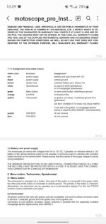
my Gauge tac is electrical and needs an input for rev bar! It’s common to plug the rev bar wire to either one of the signal generator wires as long has it’s on the lower one!


so I’m trying to figure out which of the two wire is low voltage


thanks for the help in advance
 
Last edited:
The two wires form the circuit to trigger the ignitor….far as I can tell, the ignitor sends a weak current to the signal generator setup ….this current gets magnetically disrupted when the metal tab on advancer spins by the signal coils creating a pulse to theignitor.
 
The motogadget motoscope manual says this

yellow wire - tach - to ignition coil clamp 1 (do not connect to high voltage parts)

8.2 Tachometer (Exact words from user manual)
All ignition systems that work with ignition coils are compatible. Connect the yellow connection cable
to terminal 1 (switched ground from the ignition box) of any ignition coil.
Connection to CDI ignitions (scooters, quads, enduros) is possible with the separately available
motogadget ignition signal pickup (item 9000001).​

The ignition system must be fault-free for the speed display to function correctly. Settings must also be made in the instrument setup. Please follow the instructions in the corresponding chapter..
CAUTION! THE YELLOW CABLE IS CONNECTED TO THE PRIMARY CIRCUIT OF THE IGNITI-
ON COIL. IT MUST NEVER COME INTO CONTACT WITH THE HIGH-VOLTAGE CIRCUIT


Not sure where I make this connection!
 

Attachments

  • photo63996.jpg
    photo63996.jpg
    73.9 KB · Views: 0
Page 1-5 in the factory service manual describes how the signal generators work. In essence, a small AC current is created when the iron rotor passes the signal generator coil. This current in part triggers the ignitor to fire the appropriate coil.
 
The motogadget motoscope manual says this

yellow wire - tach - to ignition coil clamp 1 (do not connect to high voltage parts)

8.2 Tachometer (Exact words from user manual)
All ignition systems that work with ignition coils are compatible. Connect the yellow connection cable
to terminal 1 (switched ground from the ignition box) of any ignition coil.
Connection to CDI ignitions (scooters, quads, enduros) is possible with the separately available
motogadget ignition signal pickup (item 9000001).​

The ignition system must be fault-free for the speed display to function correctly. Settings must also be made in the instrument setup. Please follow the instructions in the corresponding chapter..
CAUTION! THE YELLOW CABLE IS CONNECTED TO THE PRIMARY CIRCUIT OF THE IGNITI-
ON COIL. IT MUST NEVER COME INTO CONTACT WITH THE HIGH-VOLTAGE CIRCUIT


Not sure where I make this connection!

Hey ED!

I do not have the factory manual but do have a physical copy of the clymers for my motorcycle

I read through initial troubleshooting pages but still wasn't able to figure out what the ideal connection for the yellow wire would be in my scenario!
 
Page 1-5 in the factory service manual describes how the signal generators work. In essence, a small AC current is created when the iron rotor passes the signal generator coil. This current in part triggers the ignitor to fire the appropriate coil.

If I'm reading the manual right the ideal connection would be on orange/white wire that goes from the ignitor unit to the coils!
 
If I'm reading the manual right the ideal connection would be on orange/white wire that goes from the ignitor unit to the coils!

I don't believe so. That O/W wire constantly has 12v on it.

Here's the way I read the wiring diagram for the GS650G.

Starting with the ignition fuse, once the ignition switch is turned on the ignition fuse sends current up to the handle bar Engine kill switch. If the kill switch is closed, current will then continue on a O/W wire and power up BOTH coils AND the Ignitor box (IB). The primary side of each coil provides a separate ground path for each coil back to IB, B/Y for the 2/3 coil and W for the 1/4 coil. The IB is grounded through the B/W coming out of the IB so that BOTH coil primary circuits have current flowing through them and therefor BOTH coils are being charged up, waiting to be discharged.

Meanwhile, as Nessism described above, when the crankshaft turns, the signal generator generates a weak signal on the appropriate wire, either the G wire or the R (I can't tell if it is red or B brown from the wiring diagram, so I'm gonna call it R) wire going from the signal generator to the IB. That weak signal will trip the appropriate transistor momentarily interrupting the ground for the appropriate coil causing it to generate a spark. (Note that the O/W wire current is NOT interrupted)

So I would guess that either the B/Y or the W wire coming from the ground side of a coil would allow your RPM gauge to see the momentarily current interruption.
And of course maybe the weak Signal Generator signal is what the RPM gauge is designed for.

As you can see, I can't answer your question but only describe how the current ignition circuit works.
And as generic manuals leave a lot to be desired it may be time to contact your RPM vendor.
 
Last edited:
I don't believe so. That O/W wire constantly has 12v on it.

Here's the way I read the wiring diagram for the GS650G.

Starting with the ignition fuse, once the ignition switch is turned on the ignition fuse sends current up to the handle bar Engine kill switch. If the kill switch is closed, current will then continue on a O/W wire and power up BOTH coils AND the Ignitor box (IB). The primary side of each coil provides a separate ground path for each coil back to IB, B/Y for the 2/3 coil and W for the 1/4 coil. The IB is grounded through the B/W coming out of the IB so that BOTH coil primary circuits have current flowing through them and therefor BOTH coils are being charged up, waiting to be discharged.

Meanwhile, as Nessism described above, when the crankshaft turns, the signal generator generates a weak signal on the appropriate wire, either the G wire or the R (I can't tell if it is red or B brown from the wiring diagram, so I'm gonna call it R) wire going from the signal generator to the IB. That weak signal will trip the appropriate transistor momentarily interrupting the ground for the appropriate coil causing it to generate a spark. (Note that the O/W wire current is NOT interrupted)

So I would guess that either the B/Y or the W wire coming from the ground side of a coil would allow your RPM gauge to see the momentarily current interruption.
And of course maybe the weak Signal Generator signal is what the RPM gauge is designed for.

As you can see, I can't answer your question but only describe how the current ignition circuit works.
And as generic manuals leave a lot to be desired it may be time to contact your RPM vendor.

Thank you for this response!


this is what i was looking for
you're right O/W wire has constant 12v and won't be an ideal connection for Tach
So it's either going to be B/Y or white wire
But also waiting for the confirmation from manufacturer as I've shared both coil pictures and wiring diagram so hopefully they mention the same thing!


Thanks again!
 
It's definitely B/Y or White wire!


After reading my email I was going through it again this morning just to realize the coils on the image have a + or - sign associated to them!

So yellow will go on - terminal on the coils which is B/Y or White wire
 
Back
Top