• Required reading for all forum users!!!

    Welcome!
    Register to access the full functionality of the GSResources forum. Until you register and activate your account you will not have full forum access, nor will you be able to post or reply to messages.

    A note to new registrants...
    All new forum registrations must be activated via email before you have full access to the forum.

    A Special Note about Email accounts!
    DO NOT SIGN UP USING hotmail, outlook, gmx, sbcglobal, att, bellsouth or email.com. They delete our forum signup emails.

    A note to old forum members...
    I receive numerous requests from people who can no longer log in because their accounts were deleted. As mentioned in the forum FAQ, user accounts are deleted if you haven't logged in for the past 6 months. If you can't log in, then create a new forum account. If you don't get an error message, then check your email account for an activation message. If you get a message stating that the email address is already in use, then your account still exists so follow the instructions in the forum FAQ for resetting your password.

    Have you forgotten your password or have a new email address? Then read the forum FAQ for details on how to reset it.

    Any email requests for "can't log in anymore" problems or "lost my password" problems will be deleted. Read the forum FAQ and follow the instructions there - that's what we have one for...

  • Returning Visitors

    If you are a returning visitor who never received your confirmation email, then odds are your email provider is blockinig emails from our server. The only thing that can be done to get around this is you will have to try creating another forum account using an email address from another domain.

    If you are a returning visitor to the forum and can't log in using your old forum name and password but used to be able to then chances are your account is deleted. Purges of the databases are done regularly. You will have to create a new forum account and you should be all set.

Cam Chain Links Out of Synch

  • Thread starter Thread starter Suzuki_Don
  • Start date Start date
S

Suzuki_Don

Guest
The following diagram from the Suzuki Factory GS650E Workshop Manual does not make sense to me. Can someone explain please?

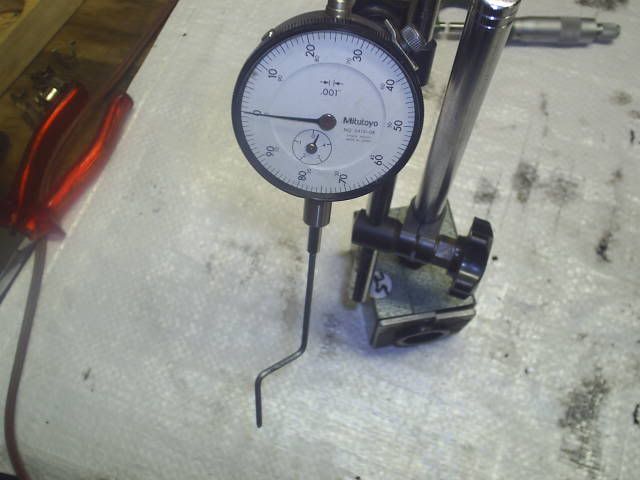
When I am doing my cam timing the manual says there should be 19 pins between the #2 and #3 arrows on the respective cam sprockets.


GS650ECamTiming.jpg


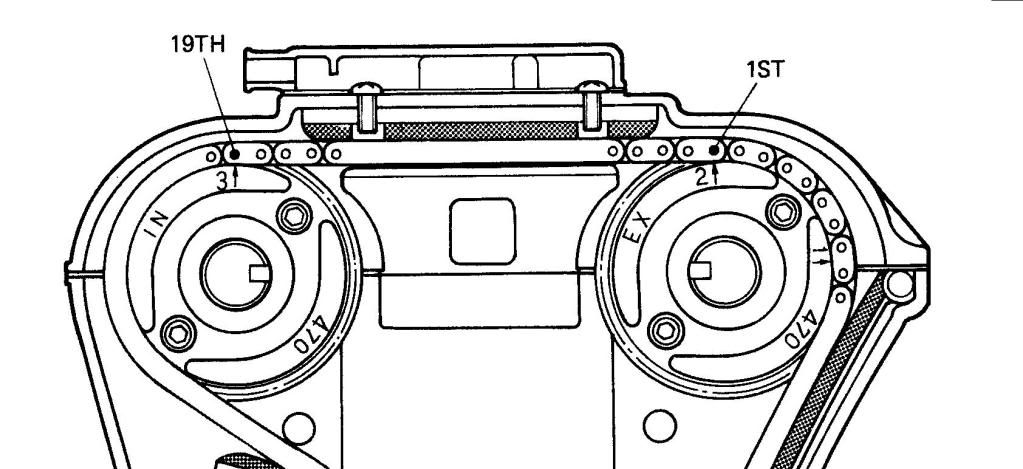
It will be seen by the above diagram that the 1st pin is on the right hand side of the outside chain link. So in my calculations the 19th pin should also be on the right hand side of an outside link. As both are odd numbers. Yet the manual shows 1st pin on right side and 19th pin on left side of a link.

Am I going crazy. Did Mr Suzuki get it wrong. Am I seeing things the wrong way round.

Do I just count 19 pins and leave it at that or does the pin on the left side of the link above arrow #3 on intake sprocket have to line up. This means it would be eith 18th or 20th pin.

Thanks in anticipation.
 
Last edited:
It's just a screwed up illustration. As long as you have the right number of pins between the timing marks you're okay.
 
Yes it looks like the diagram is wrong.

On my GS750 which has 20 pins between the arrows for correct timing, the pins line up like your image.
 
Just think of odd and even numbers. Any odd number will be the same pin on each link.
 
Yes it looks like the diagram is wrong.

On my GS750 which has 20 pins between the arrows for correct timing, the pins line up like your image.
Same here 20 pins. Suzuki probably used the same image for both pin counts.
 
NO the diagram is not wrong. I hate using absolutes but most US models have exhaust #1 pointing directly to the cylinder head surface with 20 pins between #2 & #3. The Aussie models are different, what else is new? Aussie also received the Mikuni VM30 on the GS1000 which no one else received

Have a look at the link below and scroll down to the bottom and you will see the same configuration used on a Aussie GS1000S "Valve Timing for the GS1000ST" That manual shows the Aussie & Canada (Other) models, the Canadian model shows the familiar twenty pin count.

http://www.theflyingbanana.com/gs1000s2.htm
 
Last edited:
I got interested and pulled the GS1000 service manual to compare apples & oranges. What is significant about this drawing is the exhaust cam is rotated CCW by one tooth. The arrow below the #1 normally points to the cylinder head surface in the US/Canadian models. Your GS650 manual illustration does not show that. So when installing your exhaust cam follow the normal installation of finding TDC F1.4, then pull up tight on the cam chain & position the exhaust cam as shown. Count 19 pins and that will ensure the #3 arrow on the intake cam is facing staright up or perpendicular to the cylinder head surface. The pin count is off but the #1, #2 & #3 arrows are correct
 
Last edited:
Thanks for the extra detail SUPERTRAP. Looks like I might have to look into this a bit deeper.

The motor is actually an Aussie 550 bottom end and 650 cylinder head with U.S 650E cams (different from GS650G) and sprockets. So I am not sure where to go from here.

Anyone out there with a 650E model that knows how to set the cams. Any advice from someone that's done it would be very useful.
 
I would set it up for the US cam timing with the #1 arrow parallel with the case, count back 19 pins with # 2 and 3 strait up. I doubt there is any differences in the cranks. With two people, it is possible to rotate a cam without having to tear it down again or remove the cam chain. A friend of mine rebuilt two GS 750's and got the cam timing off on both bikes. We were able to rotate the crank to the timing mark, remove the bearing caps from the cams, having one person hold tension on the chain and get enough slack to roll the cam up the chain, disengage the sprocket and realign the cam and roll it back down the chain to the proper timing mark. It is most likely easier on the 750's because of the sprocket idler in the middle of the cams for a little extra slack when removed, but can be done (very carefully). The one bike we have done runs fine now. Not a recommended procedure but possible if you are patient. Here is a link to the 650E manual: http://www.mtsac.edu/~cliff/storage/gs/GS650E_Service_Manual.pdf
 
Last edited:
Those lines on the end of the cams should face each other as well - that's another check. Looks to me as if the picture is right.
 
Those lines on the end of the cams should face each other as well - that's another check. Looks to me as if the picture is right.

Except that the pin shown as the 19th is actually the 20th pin in the diagram.

I have worked out that there are different size sprockets used on the respective motors. Mine has 30 teeth on the camshaft sprocket which means 15 teeth on the crank and the 650G has 34 teeth on the cams and 17 on the crank. That would be why the "G" model needs to go to the 20th pin to allow the chain to go over the larger sprockets and the "E" is reduced to the 19th pin to allow for the smaller sprockets.
 
Last edited:
Aah yes, silly me, I see what the confusion is. I think the words are right and the bottom part of the diagram but not the top half.

Have a look at the picture on here for the GS1000:
http://www.theflyingbanana.com/gs1000s2.htm

You'll see at the bottom of the page what I mean about the slots on the cams - they're the bits coloured green. I'm pretty sure this holds up for all Suzuki cam shafts - I can't think of when it didn't apply.

OK thanks HAMPSHIREHOG. I will set it up as suggested: #1 arrow lined up with the top face of head, #2 arrow pointing straight up and #3 arrow lined up vertical with 19th pin attached and hope that will work for me.

Thanks everyone for the advice and TFB even though you did not reply your website contribution is invaluable.
 
Last edited:
Just a quick update for anyone doing the timing on a GS650E (as there is not much info available on this model as most 650s are the "G" model).

I fitted and timed the camshafts with the motor at TDC #1 cylinder on compression stroke.

Exhaust Cam #1 arrow about 1/2 a tooth above upper cylinder head surface. Remember the arrow would not line up exactly with the surface. It was either a bit above or a bit below.

Inlet Cam: Counted 19 pins from the pin above #2 arrow on exhaust cam to pin above #3 arrow on intake cam.

Then released cam chain tensioner and rotated motor half a dozen revolutions to check timing lined up again OK on the compression stroke on #1 cylinder.

I then checked the opening and closing of the intake and exhaust valves in crankshaft degrees and all the readings were within spec.

So I know the cams are installed correctly. One tooth out on either cam equates to 12 degrees so it is pretty easy to see if you are out of spec or not.
 
If it was my engine I would get a dial indicator and degree wheel and make sure. My cams set up at stock were WAY off, and now you are mixing and matching parts from different bikes from different continents:eek:
Definatly a multinational motor you have there.
 
If it was my engine I would get a dial indicator and degree wheel and make sure. My cams set up at stock were WAY off, and now you are mixing and matching parts from different bikes from different continents:eek:
Definatly a multinational motor you have there.

Funny you should say that as I picked up a dial gauge for $25 at a Ford swap meet last weekend. It should do the job nicely.

S3010099.jpg
 
Back
Top