-
Required reading for all forum users!!!
Welcome!
Register to access the full functionality of the GSResources forum. Until you register and activate your account you will not have full forum access, nor will you be able to post or reply to messages.A note to new registrants...
All new forum registrations must be activated via email before you have full access to the forum.A Special Note about Email accounts!
DO NOT SIGN UP USING hotmail, outlook, gmx, sbcglobal, att, bellsouth or email.com. They delete our forum signup emails.A note to old forum members...
I receive numerous requests from people who can no longer log in because their accounts were deleted. As mentioned in the forum FAQ, user accounts are deleted if you haven't logged in for the past 6 months. If you can't log in, then create a new forum account. If you don't get an error message, then check your email account for an activation message. If you get a message stating that the email address is already in use, then your account still exists so follow the instructions in the forum FAQ for resetting your password.Have you forgotten your password or have a new email address? Then read the forum FAQ for details on how to reset it.
Any email requests for "can't log in anymore" problems or "lost my password" problems will be deleted. Read the forum FAQ and follow the instructions there - that's what we have one for...
-
Returning Visitors
If you are a returning visitor who never received your confirmation email, then odds are your email provider is blockinig emails from our server. The only thing that can be done to get around this is you will have to try creating another forum account using an email address from another domain.
If you are a returning visitor to the forum and can't log in using your old forum name and password but used to be able to then chances are your account is deleted. Purges of the databases are done regularly. You will have to create a new forum account and you should be all set.
You should upgrade or use an alternative browser.
")
GS1000G Shopper
Guest
GS1000G Shopper
Guest
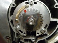
The crank has a bump on it where the OEM timing set rests. This is what turns the crank when you place a wrench on it. When #1 is at TDC, the bump is about 20 degrees beyond the factory timing mark (which cannot be seen under the plate). Indicated TDC can be anywhere on the wheel, so I used the area from 9 o'clock to 11 o'clock since there was nothing else there. I went in 10 degree steps for the numbers so as to make them larger. There are 5 degree marks from 0-45 degrees.
Using this data, I was able to create a mounting plate for the VR sensor that has timing marks built in to it. The wheel I designed was a common 36-1, so each tooth is 10 degrees. It is the same OD as the one I am currently using. No sense to totally reinvent the wheel.

As Arttu has noted earlier in this thread, these parts are too costly to make just one, at least in metal. The estimate for the plate was about $130 and the metal wheel was about $125. I realize there is next to no demand for this stuff, but thought it would be nice to save my work. Using inexpensive plastic parts (< $20 each), if I can get everything to line up, I will save the files in Shapeways and e-Machine shop for future use should anyone want to spend the money for metal parts. This should work for any 4 cylinder GS of this era that has the same crank opening.
Arttu advised the crank sensor was from an 80's-90's Suzuki dirt bike. I did some research & found the OEM part number was 32150-05D00. An eBay search turned these up new aftermarket for $9 each.
Plate with integral timing marks (for some reason, Shapeways considers this part too small to create in anything but plastic, but e-Machine Shop can make it in aluminum) and 36-1 wheel. I have updated this drawing to incorporate a tooth #1 angle of 100 degrees. The suggested angle for a 4 cylinder engine is 90-120 degrees.
[URL=http://s243.photobucket.com/user/P_Account0818/media/1981%20Suzuki%20GS1000G/Fuel%20injection%20project/Microsquirt%20V3/GS%20plate%20wheel%200615_zpsadwih8rm.png.html]
 [/URL]
GS1000G Shopper
Guest
It's worth of noting that this VR sensor isn't tested with 36-1 wheel of that size. So there is a risk that teeth width and spacing gets too small for the sensor. Though it might work just fine.
And I can still deliver complete trigger set for about $100 (plus shipping) if anyone needs one.
")
GS1000G Shopper
Guest
Another concern is that 3D printed wheels are not 100% steel- Shapeways uses a 60% steel / 40% bronze mix. Since bronze is non-ferrous, this will likely affect the performance with a VR sensor. A MS user poiinted out the 3D part may not be suited for high RPM use. I have emailed Shapeways to see if this is a concern. I found a GE mini jet engine that was 3D printed and spun to 33K RPM.
I'm waiting to get some more info and if this appears feasible to save shipping costs will order all of the parts in cheap plastic to see how they fit.
The price difference is significant. e-Machine Shop wants over $500 to make a GS wheel and cannot easily print the text/mark, while I can get the same part made in 3D with the text/mark for a little over $100.
Did you check out the aftermarket RM250 sensor on eBay? They are selling for $9 each with free (US anyway) shipping. I put in some European countries and the shipping cost jumped to over $50, or $62.50 for 10. Like the other parts, you'd have to buy in bulk.
EDIT
I designed a 24-2 wheel and pasted it onto the plate diagram. It lined up perfectly with the timing marks, each tooth is 15 degrees vs the 10 degrees for the 36-1. I have revised this drawing to use a tooth #1 angle of 105 degrees. For 4 cylinder engines, the suggested range is 90-120 degrees.
[URL=http://s243.photobucket.com/user/P_Account0818/media/1981%20Suzuki%20GS1000G/Fuel%20injection%20project/Microsquirt%20V3/24-2%20wheel%20and%20timing%20plate_zpsujwxmptu.png.html]
 [/URL]
Yes, it has been like that every time I have bought these sensors. In Europe they seem to cost about $40 each and in USA $10-20. And for some reason every seller in USA likes to charge around $50 for shipping which is quite steep as you can often get similar packages shipped for $10-15. So yes, I need to buy them in bulk to get price even somewhat reasonable.Did you check out the aftermarket RM250 sensor on eBay? They are selling for $9 each with free (US anyway) shipping. I put in some European countries and the shipping cost jumped to over $50, or $62.50 for 10. Like the other parts, you'd have to buy in bulk.
If steel in printing alloy is stainless it isn't too good for the VR sensor either. Some ferrous stainless alloys may work but most likely the response is still weaker than with normal mild steel. My feeling is that strength isn't that big concern. Since the diameter is rather small the centrifugal forces should be reasonable.
coombehouse
Guest
GS1000G Shopper
Guest
My wheel design simplifies installation and use by having tooth #1, sensor alignment, and a timing mark present. I have some more work to do on it based upon information learned from the Microsquirt manual. It's currently at a 30 degree angle and this needs to be 90-120 for optimum timing. Looking at my layout, I can easily revise it to 105 degrees.
My plate design has timing marks, something no one else has done. Checking timing is vital in Mega/Microsquirt installations.
These parts if produced would come from the US, which would save on shipping for domestic users.
At any rate, despite the continued criticism, I enjoy designing parts, and how I spend my time is my business. A year ago I lacked the skills to design a wheel and it has been an enjoyable learning experience that I've carried over to other projects. I've expanded on this and laid out a wheel for the GSX-G engine for when I do a similar conversion to it. This took about an hour since it was so similar to what I had made.
GS1000G Shopper
Guest
ITB mode setup thread on MS Extra forum
I have been doing some reading on what is called Individual Throttle Body mode or ITB. It appears most Megasquirt setups use speed density (SD), while others use Alpha-N (A-N). ITB is supposed to be a hybrid mode from the two that can be beneficial for a setup like mine. The process involves road testing with an operable SD or A-N tune, so I am not at that point just yet, but I have set up the Microsquirt per the below link to output on pin 7 (fast idle) to a temporary lamp at the handlebars when the engine is at 90 kpa. This is supposed to be similar to a dyno run, and the recorded data can then be analyzed and used for ITB mode. I've ordered a serial to Bluetooth adapter so I can log data on my phone via the Tuner Studio android app called Shadow Logger.
I have never tried the ITB mode as I mainly play with boosted engines and the ITB mode doesn't support them. But even plain Alpha-N works very well on this kind engines. And you can combine MAP value on it by selecting "multiply MAP" option which basically scales the injection amount by MAP value. Speed density usually don't work too well with individual throttle bodies. Since the A-N is much simpler to tune I would start with it and consider moving to the ITB mode once the engine is running well and all the bugs are ironed out.
GS1000G Shopper
Guest
The end result was really close- all it took was a slight turn of the plate once installed and I had the marked tooth aligned on 0. Note that the center of each tooth aligns with the 0, 15, 30, and 45 degree marks, which verifies the timing marks. Each tooth is 15 degrees since 360 degrees / 24 teeth= 15 degrees per teeth.
Attachments
GS1000G Shopper
Guest
I'm reading and trying to see what is causing the high idle. I thought I had misaligned one of the old throttle bodies, but it was replaced. I don't see any vacuum leaks, all hoses are in place and nothing is dry or cracked. It looks like I'll have to tweak the VE table.
My Bluetooth adapter arrived so I can ride & log now once I get past the high idle.
Here's a link to a decent and relatively inexpensive WB O2 meter:
http://wbo2.com/
If you have decent soldering skills then you can order the DIY kit and save some bucks.
Everything is back together and now I'm working through the intricacies of Microsquirt tuning. The high idle remains, it was about 2500 when I started it, and then when I checked the timing with a light, I saw I was 5 degrees off. I changed my tooth #1 angle and this gave me correct timing, but it also gave me another 500+ RPM at idle.
I'm reading and trying to see what is causing the high idle. I thought I had misaligned one of the old throttle bodies, but it was replaced. I don't see any vacuum leaks, all hoses are in place and nothing is dry or cracked. It looks like I'll have to tweak the VE table.
That high idle means the engine must get too much air from somewhere. Have you already adjusted the throttle stop (idle adjustment) to minimum? As you noticed the ignition timing affects to idle rpm quite strongly. The VE table has only secondary effect to the idle rpm. You want to tune the VE table so that you get good AFR and steady running at the idle. Actual rpm adjustment is then done by idle screw. Of course if your VE table is badly off it will drop rpm too but if your idle screw is correct then you can't get the rpm from correct idle to 3000rpm range by VE table.
GS1000G Shopper
Guest
I tested my MAP sensor and found it was bad. I think this is the root of my idle problem. I managed to break an injector connector and nick an injector o-ring, so I'm on parts hold for the connector. The fuel leak from the injector ruined the AMP connector seal, so I had to replace it as well.
I'll update once it is back together.
ruili
Guest
instead of using a coil driver and ignition coil wouldn't it be cheaper and better to just use lsx coils? hotter spark, and built-in drivers. or would they use up too much power?
GS1000G Shopper
Guest
I didn't check the power draw for the LSX coils, but did look them up for this reply.instead of using a coil driver and ignition coil wouldn't it be cheaper and better to just use lsx coils? hotter spark, and built-in drivers. or would they use up too much power?
The specs I found for an MSD LSx coil were:
Resistance: .57
Inductance: 5.8
At 3 ms of dwell, each coil would draw 5.37 amps. The Neon super coil at the same dwell draws about 4.5 amps. The Megamanual page below says the LSx coils like 5.6~5.8 ms of dwell for optimum performance. That's about 9 amps each using the above specs.
Since these are individual coils, you'd be firing 2 of them with any given output from the Microsquirt. One would be a "wasted" spark so it would not have the higher current draw, but even if it were half you're looking at over 13 amps.
In one of my datalogs I made while the engine was running, I noted the volts were consistently 13.8, so the Neon super coil is not killing the charging system. The bike has the Compufire 3 phase regulator rectifier recommended on this site.
Another problem with doing this would be their size & having to use 4. There's only so much room under the frame tubes. You then have 4x as much wiring, to include heavier gauge power feed, plus there is still added wiring via two recommended capacitors.
I'd have to find the dimensions for them, apparently the LS2 coils are narrower but perhaps taller.
As for cost, I paid about $37 for the Neon super coil and another $10 for the wiring pigtail (plus shipping). A few $ could be saved by making your own connector. I used my (free) stock ignitor box with a $4 Radio Shack perfboard, and an $18 pair of BIP373 transistor kits, so this was $61 total (plus shipping). The cheapest new LS2 coil I saw on eBay was almost $20, that's over $75 for the coils, plus there is another $14 for 4 connectors with terminals, so that's $89+ (plus shipping) and then you still need to add capacitors for optimum performance.
In summary:
Cheaper? No.
Better? Not likely. More draw required for the improved output, plus added wiring and then possibly not enough room. I'd say the LSx coils would likely get the nod for an automotive project where there is more room and more amperage available.
At this point, as the saying goes, the coil isn't broken, so I'm not going to fix it.
Guest
Guest
stock neon coils have no issue lighting off heavily boosted neon motors.... like 650hp on up.
it may decrease your current and still run the engine just fine.
i bought a setup off of arttu as well but am working on my turbo plymouth reliant right now so the bike still waits for EFI. i have my gsxr throttle bodies and the pump controller but i still need to get a microsquirt and fuel pump.
i just realized that i have a stock neon coil and pigtail sitting on a parts neon in my yard that im slowly stealing things from lol. less stuff to buy.
Brian
GS1000G Shopper
Guest
I'll likely use the Subaru coil on the GSX1100 project I'm planning now. The parts bike makes an easy test mule for sizing things up.
Glad to hear you'll be undertaking this project at some point, I hope my documentation of the good, the bad, and the ugly here will help.