Announcement

Collapse
No announcement yet.

1981 gs750 (gs750e) Retro Racer project

Collapse
X
 
  • Filter
  • Time
  • Show
Clear All
new posts

  • LarsKroghStea
    replied
    Haven't ordered anything for the bike in a couple of years, so I decided to fix a problem I've postponed for a while. I've bought some really cheap turn signals from ebay earlier, and they've all turned out to be crap. In sunlight it's almost impossible to notice when they're blinking. Two of the sets have decent light output, but they either look really cheap or they're too big. So, as a "back on the horse"-gift for my self, I ordered the Mo.blaze tens 1 for the front turn signals. Maybe not worth the money, but they are exactly what I was looking for A step up in safety too.


    Image from the web:


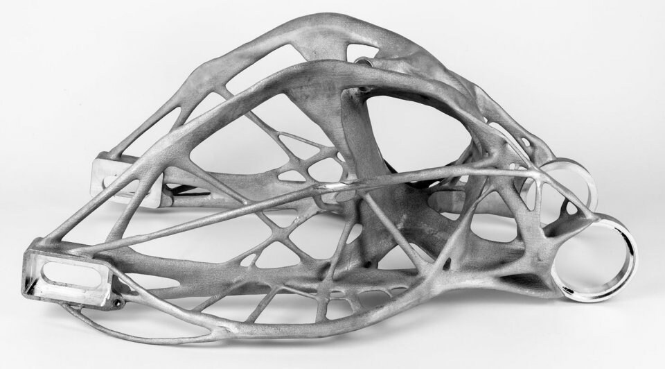
    I 3D-printed these headlight-brackets to test headlight placement, and I'll make new ones in aluminum with an M8 threaded hole for the Mo.blaze tens'.


    Leave a comment:


  • Suzukian
    replied
    Thank You! The model unfolds flat. I may release it, not sure yet. It would be a complicated built, but more intricate, than complicated. This was all done with Rhino 3D.

    Leave a comment:


  • LarsKroghStea
    replied
    Originally posted by Suzukian View Post
    I cannot make a swing arm like that. I can make you a bulk head for a Blackhawk helicopter, or CH53 series, but I know my limitations. The NURBS modeling is Rhino is so fluid, once you start working with it, and with it's smash, squish, and unfolding a developable surface functions, you'll find it's a hard program to beat. It exports into over 60 different formats, so you can make a model on Rhino that 3DS Max, or Cinema Las Vegas Pro can read. It's very compatible.

    One of my Paper models.

    Stealstar.jpg

    That's awesome

    Leave a comment:


  • Suzukian
    replied
    I cannot make a swing arm like that. I can make you a bulk head for a Blackhawk helicopter, or CH53 series, but I know my limitations. The NURBS modeling is Rhino is so fluid, once you start working with it, and with it's smash, squish, and unfolding a developable surface functions, you'll find it's a hard program to beat. It exports into over 60 different formats, so you can make a model on Rhino that 3DS Max, or Cinema Las Vegas Pro can read. It's very compatible.

    One of my Paper models.

    Stealstar.jpg

    Leave a comment:


  • LarsKroghStea
    replied
    Originally posted by Suzukian View Post
    If you have any children, or grandchild, or related child, in school, you can get a full working version of Rhino 3D NURBS Modeling for 3 computers for only $200 bucks.
    Will definitely test that out. I remember NURBS becoming a thing, but Youtube wasn't a thing when I dabbled in 3D modelling, so the learning curve was too steep. I've looked for a way to model more organic shapes, so Rhino looks interesting.

    One thing i did try, was "generative design". For those of you not familiar, you specify mounting points, maximum dimensions and interfernce points, materials and load requirements etc. Fusion360 then calculates an organic shape meeting your requirements, and at the same time optimizing for weight/material use. I made brackets for my headlight, but they looked too futuristic for my style.

    For reference, this is how a swingarm looks when it's generated only for purpose, not for looks:


    You can read more about it here: https://www.autodesk.com/campaigns/g...ng-motorcycles


    And here's a complete elektric bike. The weight savings for theese designs are typically between 30% to 50%, while retaining torsional rigidity optimized for your application:


    More pictures here: https://www.carbodydesign.com/2016/0...bionic-design/


    Well, I digress.. But I am thankful for the NURBS-info. I'm making a small housing for the Motoscope Mini, as I want to move it from the headlight to the top triple. Rhino/NURBS might be perfect

    Leave a comment:


  • Suzukian
    replied
    You are an engineer. You just don't have a piece of paper saying so.

    If you have any children, or grandchild, or related child, in school, you can get a full working version of Rhino 3D NURBS Modeling for 3 computers for only $200 bucks. It is the same as the commercial version, and you can use it for profit. You can give it to a minor as a gift, you just need their student I.D. to buy it. It allows you to mount it on 3 different computers. It was used to make the Space Shuttle Tiles, many sets for movies, Nike Sneakers, the list goes on. It's N.U.R.B.S. modeling capabilities are unmatched. 1000's of videos using Rhino on YouTube.


    Design, Model, Present, Analyze, Realize...


    N.U.R.B.S.(Non-Uniform Rational B-Splines​) in a nutshell:

    NURBS in 3D modeling are used to create curves and curved surfaces. Whenever you need to create a unique or unusual curved shape quickly, without worrying about painstakingly carving it out by way of pure polygonal geometry alone, NURBS curves make following any example easy.​

    Leave a comment:


  • LarsKroghStea
    replied
    Originally posted by Suzukian View Post
    I wasn't here when this thread started, having run through it very quickly, awesome CAD skills, I use Rhino3D. I used to program 3,5 and 8 axis CNC machines. Seeing what you are doing at home is very inspiring. You are a 1%'er!!
    Thanks! I don't have anyone to compare myself to, as the guy who owns the CNC only uses it for wooden cabin signs I use Fusion360 (non commercial license) for modelling 3D printed parts. They arre printed via Ultimaker Cura. For CNC, I used the software my friend already had, Vectric Aspire for modelling and setting toolpath etc., and NC Studio for controlling the CNC router. About 25 years ago, I got hold of a copy of 3D Studio max and did some 3D modelling (waiting 30 hours for a picture to render..), and adapting basic understanding of 3D modelling to CNC/3D printing wasn't too much work.
    I really like working with these machines, and my wife always say I would be happier if I was an engineer. Maybe she's right, but I'm turning 50 next year, so I think I'll just stick to what I do and try to set aside some time for hobbies.
    It's nice to know that we have a CNC expert on the board, and I'll probably message you when I get my own CNC up and going. Milling the parts I have now was a lot of work, as neither of us had any experience with rpms and toolspeed for effective machining of aluminum (Also; had to google 8 axis CNC.. looks awesome )

    Leave a comment:


  • Suzukian
    replied
    I wasn't here when this thread started, having run through it very quickly, awesome CAD skills, I use Rhino3D. I used to program 3,5 and 8 axis CNC machines. Seeing what you are doing at home is very inspiring. You are a 1%'er!!

    Leave a comment:


  • LarsKroghStea
    replied
    One final point for today: I read through my discussions with posplayr about correctly grounding the R/R etc (https://www.thegsresources.com/_foru...the-1982-gs750). I learned a lot from it, and I think he and I were essentially aggreeing in the end. One thing I will stand corrected on not beeing to clear on, is that the SPG (in my drawings) he was going on about, is in reality through a bolt to the frame. That means the R/R is grounded to; the frame, the loom and the battery, as he recommended There's also a common ground at the front of the frame (for handlebars, lights etc), and that groundpoint has it's own wire to the SPG. The ground for the ignitor and horn is through the front ground point, but I'm not changing my drawings as I would rather spend time on the actual wiring

    The rear lights also has their grounding through SPG.

    Feel free to ask or comment, I'm still figuring this out

    In the app for the Mo-unit blue (as it is now called, I still have the same unit) I can turn on and off the different inputs and outputs, so it is easy to check for faults. There's also a readout for electrical current on all outputs, so I can check if I have an issue with unwanted grounding/unwanted draining of the battery.

    Leave a comment:


  • LarsKroghStea
    replied
    When researching how to route the wires, I also came upon a diagram showing how to route the cables:

    Wire routing_3 by Lars Krogh-Stea, on Flickr


    The same problem arises here, as the handles are so low, that the cables must be routet differently. I will have to do some googling to se how others have solved that problem, as I'm not comfortable with the cables going in big loops from the handlebar to the frame. In the picture, the "flat handle model" shows some degree of loop, and I think that's manageable.

    Leave a comment:


  • LarsKroghStea
    replied


    So, this is the wiring diagram for the bike:


    Noisemaker_koblingsskjema by Lars Krogh-Stea, on Flickr


    First time I wired it up, I made several mistakes:
    1. I used a lot of "velour tape" (looks like old electrical tape), because i thought it looked cool. Ended up with very a very stiff and bulky wiring loom.
    2. I didn't make the loom modular, which meant changing out parts resulted in the need to cut and resolder wires. I also got some advice to not rely too much on soldering, as the wires can become brittle and crack.
    3. I also didn't look into the original routes for the different wires. This resulted in the loom making a loop away from the frame when turning left, and getting almost too tight when turning right.
    The solution, I believe, is to:
    1. Using nylon sleeves and heat shrink the ends. This makes for a very flexible loom, that also look good.
    2. Make a better plan for the layout, and put connectors between the main loom and the removable parts.
    3. Research better routes for the cables that connect to the fork. The wires should cross from the fork to the frame in a vertical path, rather than horizontal, to eliminate the need to compensate for the turning of the handlebars.

    The solution for no.1 and 2, looks like this:

    IMG_20210517_125303 by Lars Krogh-Stea, on Flickr


    And grouping of wires looks like this:

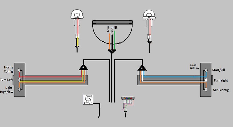
    Wiring front by Lars Krogh-Stea, on Flickr


    Routing looks something like this, but I have to compensate for the clip-ons being positioned much lower:

    Wire routing_1 by Lars Krogh-Stea, on Flickr


    Leave a comment:


  • LarsKroghStea
    replied
    Well.. I'm almost embarrassed to revive this old thread Started in 2015, and still the bike is not roadworthy (even though it was for a couple of weeks, before I started the fork swap).
    It got put in the back of the garage in '21 as my work in hospital leadership became too time consuming. This febrary, I descided to change my carreerpath and applied for a position as leadership advisor in stead. Maybe not the same long time carreer opportunities, but much less stress and no people to manage. Also the work itself is much more interesting.

    With more spare time, I've started doing some mechanical stuff again. Changed the clutch/flywheel on a Volvo V60, which was a lot of work.. Also helped my youngest son with his Audi TT. Bought a lot of new tools, and got bitten by the garage bug again Last week I dug out the old GS from the garage and rigged a workshop in one of the sheds. Spent the evening there today, and realized how relaxing it is

    I promise you guys; this summer I'm going to ride the bike a lot. And now that i've made the promise, I'll have to get it done

    I bought a new battery today, as the old one had gotten really old, and booted up the mo-unit. I cut most of the wires when switching out the stock fork for the 2005/6 GSXR fork, so the first I'll have to do is wire the bike up again. Then there's the brakes, clutch and throttle. I will also need to 3D-print a housing for the Motogadget mini.

    Here's a motivational short of the Mo-unit booting up:

    Last edited by LarsKroghStea; 06-24-2023, 02:40 AM. Reason: Typo

    Leave a comment:


  • John Kat
    replied
    Hi Lars
    How are things going?
    On my side, I'm currently restoring a GS 1000 with a GSX 1135 engine.
    I'll look through your posts but I was wondering how you solved the throttle assy on your bike?
    Given that the control switches are becoming a rarity we are almost obliged to use suitable aftermarket parts that leave an issue with the throttle assy.
    Motion Pro has apparently a suitable item (Motion Pro Push/Pull Throttle Assembly Kit for Mikuni Racing Carburetors | Kawasaki and Suzuki Motorcycle Parts | Z1 Enterprises) but what about 3D modelling a plastic part that would take the OEM throttle cable?
    Let me know your thoughts.
    Update:
    I see you used a Domino throttle assy.
    Is it the XM2 version?
    Where did you buy it from?
    Last edited by John Kat; 08-30-2021, 01:39 PM.

    Leave a comment:


  • LarsKroghStea
    replied
    Wired the bike up enough to start it today, but the throttle is stuck. It's not the wire, it's the shaft for the butterfly valves. I'll pull the carbs when I have time and clean and oil the shaft and linkage. Annoying as...!

    Leave a comment:


  • LarsKroghStea
    replied
    Originally posted by John Kat View Post
    I also ran into an issue with the wiring of my coils....
    In fact during one iteration of the bike setup, I had pulled a wire from one of the coils to an electronic tachometer.
    When I reverted the bike to OEM, it would refuse to take full rpm among other running issues!
    The reason was that I had "borrowed" the wire that is normally used for the fuel gauge to carry the tacho signal.
    When reverting to OEM, the tacho signal went to ground through the OEM defective fuel gauge.
    BTW, I'd like to buy some Dyno coils but what's your model and what cables are you using?
    The cables come as two wires with coil connectors in both ends. You cut them to length and crimp the plug connectors yourself.

    Leave a comment:

Working...
X