• Required reading for all forum users!!!

    Welcome!
    Register to access the full functionality of the GSResources forum. Until you register and activate your account you will not have full forum access, nor will you be able to post or reply to messages.

    A note to new registrants...
    All new forum registrations must be activated via email before you have full access to the forum.

    A Special Note about Email accounts!
    DO NOT SIGN UP USING hotmail, outlook, gmx, sbcglobal, att, bellsouth or email.com. They delete our forum signup emails.

    A note to old forum members...
    I receive numerous requests from people who can no longer log in because their accounts were deleted. As mentioned in the forum FAQ, user accounts are deleted if you haven't logged in for the past 6 months. If you can't log in, then create a new forum account. If you don't get an error message, then check your email account for an activation message. If you get a message stating that the email address is already in use, then your account still exists so follow the instructions in the forum FAQ for resetting your password.

    Have you forgotten your password or have a new email address? Then read the forum FAQ for details on how to reset it.

    Any email requests for "can't log in anymore" problems or "lost my password" problems will be deleted. Read the forum FAQ and follow the instructions there - that's what we have one for...

  • Returning Visitors

    If you are a returning visitor who never received your confirmation email, then odds are your email provider is blockinig emails from our server. The only thing that can be done to get around this is you will have to try creating another forum account using an email address from another domain.

    If you are a returning visitor to the forum and can't log in using your old forum name and password but used to be able to then chances are your account is deleted. Purges of the databases are done regularly. You will have to create a new forum account and you should be all set.

GS1000G mods- big bore and fuel injection

  • Thread starter Thread starter GS1000G Shopper
  • Start date Start date
No change there then. Worth a try though. Btw what is the rpm logging programme you are using. I have not seen it before. I have only ever used the trigger logger in tuner studio which I think give more info than just a trace. Could be wrong tho as I haven't used it for ages. Have you tried it?
Nick
 
That screencap was from the tachref program that must be loaded in place of the MS FW. I had forgotten about MS2 extra having a trigger/tooth logger. I did a screencap of my Megalog viewer for the tooth log here:
 
Last edited:
Yes that looks more familiar but doesn't produce any eureka moments for me. Hopefully someone else will be able to suggest a solution. I guess you have already tried changing the rising/falling edge settings in tuner studio. Other than that I would only guess that due to the wheel diameter the pickup cannot distinguish the teeth from the gaps. Having said that you would expect to get a better pulse with the wheel with less teeth as the tooth to gap ratio would be better. How about trying the small wheel with the small air gap & without spark plugs fitted to remove any variation in cranking speed. Just thinking out aloud really.
Nick
 
That screencap was from the tachref program that must be loaded in place of the MS FW. I had forgotten about MS2 extra having a trigger/tooth logger. I did a screencap of my Megalog viewer for the tooth log here:

Is this the time between pulses as reported by the mega squirt?

there is some periodicity to the pulses, along with quite a bit of randomness.

So what type of input does the mega squirt have?

This is reminiscent of the problem I had with the Innovate Sports RPM input on my WB02 setup.

Do you have a scope to look at the analog signal that the MicroSquirt is seeing? The is apparently signal with some noice. I have to ask but how are you grounded?

Have you looked at the signal to ground on the signal on the Microsquirt?
 
Last edited:
2

2

Okay, I can see what you say about someone else being able to repeat it but I think to create the initial running bike, you got seriously sidetracked.
The pictured is a 24-2 wheel and should work. You just weld a plate to your stock advancer to make it adjustable. Grind the cam chain drive teeth off though as you won't need them.
The one you saw was the older version. And I am also suspecting that maybe you need to remove the igi box between the pickup and the MS2 computer. s I think the switching unit could be built inside the MS2. And ask Arttu more how he did his. A turbo no less.
I would also say don't give up yet. And paying $150 for the Pamco thing doesn't sound cheap.
And if you need more stock GS advancer wheels and plates, I have several.
Note, the GSXR wheel is approximately 2.5" in diameter. Maybe I'llhave to rig something up and send it to you?
Laters
G
Try this link for more info.
http://ecuhacking.activeboard.com/t41688286/fuel-injected-1127/
 
I'm getting closer, fiddling around with the timing and using residual fuel pressure it actually ran for like 2 seconds. I'm not going to pursue this since the trigger wheels are now no longer a press-fit onto the rotor shaft- they're too loose after being pressed on & off a few times.

The Pamco setup should be here by next Wednesday, so I'll tinker with it and see how it works.
 
1. Is this the time between pulses as reported by the mega squirt?

2. there is some periodicity to the pulses, along with quite a bit of randomness.

3. So what type of input does the mega squirt have?

This is reminiscent of the problem I had with the Innovate Sports RPM input on my WB02 setup.

4. Do you have a scope to look at the analog signal that the MicroSquirt is seeing? The is apparently signal with some noise.

5. I have to ask but how are you grounded?

6. Have you looked at the signal to ground on the signal on the Microsquirt?

1. It's a tooth logger. It's supposed to log when the sensor sees a pulse. For what it's supposed to look like, visit this page:
http://msextra.com/doc/general/toothlogexamples.html

2. That's the problem from what I can tell.

3. Two options, one is called the opto isolator and the coil can hook up to it. I tried that first, and did a wiring mod as suggested by some folks at the MS Extra forum that came from a GSXR setup.

The other is called a VR (variable reluctor) input for that type of sensor or a Hall sensor, it has two pair of wires so a dual ignition can be run. Our GS is set up for this ideally, the pickups are 180 degrees apart. If the 1000 pickups were isolated as they are on the later 1100 engines, it would wire in perfectly. As it was here, the 1-4 and 2-3 pickups share a common (red) wire, so there are only 2 wires going to the ignitor box, not 4. My current setup has two wires in a shielded cable going back to a Weatherpack plug to connect to the MS. The shield on the cable is grounded to the frame per the instructions for this setup.

4. You're kidding, right? (I am, hence the smiley if you can't see it) :) I'm one of my friend Tkent02's worst nightmares, I buy $500 bikes and then spend thousands on them over time. I don't have the $ for an oscilloscope and don't know anyone that has one.

5. The MS is grounded to the frame on the rear master cylinder 8mm bolt. The shield as noted also grounds to the frame on the rear master reservoir 6mm bolt. I use quality ring terminals that I crimp & solder. I'm running new 6 gauge positive & ground cables from the battery.

6. I'm not sure what you mean by this. The MS has a signal ground circuit, as I recall it is common with one side of the VR inputs.
 
Yes that looks more familiar but doesn't produce any eureka moments for me. Hopefully someone else will be able to suggest a solution. I guess you have already tried changing the rising/falling edge settings in tuner studio. Other than that I would only guess that due to the wheel diameter the pickup cannot distinguish the teeth from the gaps. Having said that you would expect to get a better pulse with the wheel with less teeth as the tooth to gap ratio would be better. How about trying the small wheel with the small air gap & without spark plugs fitted to remove any variation in cranking speed. Just thinking out aloud really.
Nick
Everything done here in the past couple of days was with the 12-1 wheel.

I've posted more graphs on the MS2 forum. When I changed the noise filter amount this seemed to make a difference, but still nothing like the example page link I posted. I'm hoping to get some ideas from there.

Due to the trigger wheels starting to slip from being on & off too many times, I'm not doing anything else with it until the Pamco kit gets here.
 
1. It's a tooth logger. It's supposed to log when the sensor sees a pulse. For what it's supposed to look like, visit this page:
http://msextra.com/doc/general/toothlogexamples.html

2. That's the problem from what I can tell.

3. Two options, one is called the opto isolator and the coil can hook up to it. I tried that first, and did a wiring mod as suggested by some folks at the MS Extra forum that came from a GSXR setup.

The other is called a VR (variable reluctor) input for that type of sensor or a Hall sensor, it has two pair of wires so a dual ignition can be run. Our GS is set up for this ideally, the pickups are 180 degrees apart. If the 1000 pickups were isolated as they are on the later 1100 engines, it would wire in perfectly. As it was here, the 1-4 and 2-3 pickups share a common (red) wire, so there are only 2 wires going to the ignitor box, not 4. My current setup has two wires in a shielded cable going back to a Weatherpack plug to connect to the MS. The shield on the cable is grounded to the frame per the instructions for this setup.

4. You're kidding, right? (I am, hence the smiley if you can't see it) :) I'm one of my friend Tkent02's worst nightmares, I buy $500 bikes and then spend thousands on them over time. I don't have the $ for an oscilloscope and don't know anyone that has one.

5. The MS is grounded to the frame on the rear master cylinder 8mm bolt. The shield as noted also grounds to the frame on the rear master reservoir 6mm bolt. I use quality ring terminals that I crimp & solder. I'm running new 6 gauge positive & ground cables from the battery.

6. I'm not sure what you mean by this. The MS has a signal ground circuit, as I recall it is common with one side of the VR inputs.

There are some really in expensive o scope options these days. For $50 you can convert an I phone.

https://itunes.apple.com/us/app/oscilloscope/id388636804?mt=8

also

http://www.amazon.com/gp/product/B004DE31U0/ref=ox_sc_act_title_1?ie=UTF8&psc=1&smid=A2WRUBMLJPZ2AL

If you have a laptop to drag into the lab (err gaagrge) then this looks like it would be worth the money.

http://www.poscope.com/poscope-mega1-bundle-82

This was just a quick look.

It looks like the MS is a real hobby kit and you are encouraged to modify the PCBA's to make it work. This is really where you need a Oscope to see what is happening.

http://msextra.com/doc/ms1extra/MS_Extra_Ignition_Hardware_Manual.htm#hall

I need a wheel sensor for a speed input to my LM-2 and I picked up a relatively expensive sensor, but since it was on ebay I got two for only $20 ($10 a piece). Signal conditioning whether it is at the sensor or inside the MS is going to be pretty critical to getting a repeatable signal.

If you look at the attached figure, it looks like the same signal you have, but your noise is much worse; same spectral content.
 
Last edited:
I found that pulling plugs eliminates the dips so you get a better picture of how the wheel is being read. I also learned how to export only the graph part from the log viewer. Here are a couple of shots with the 12-1 with no noise filtering and no time modifications (the only 2 variables in Tuner Studio).

All things considered, the readings are not too bad. Apparently the longer/shorter bars are due to inconsistent gaps in the wheel. The really long ones are the missing tooth/teeth.
12-1:
Toothandtimezero0623_zpsd681d8da.png


24-2:
24-2zero-zero0623_zps4e1f6c23.png
 
The 12-1 graph looks like it should work. It seems that the 24-2 is missing one tooth if I counted it right?

Just for reference, here are a couple of additional photos of my 24-2 setup. It seems to work pretty well now. Though I had some noise at higher rpms. I had to add a series resistor between the sensor and ECU to get it working up to 10 krpm.
24_2_trig1.jpg

24_2_trig2.jpg
 
I counted 10 short and 1 long on the 12-1, and 20 short and 1 long on the 24-2 for each graph. I counted 11 teeth on the 12-1 and 22 on the 24-2 for each wheel, I'm not sure what they are supposed to be on the graph so I looked at the example page.

I counted 34 on the 36-1 example on the MS page so it seems my graph is correct. I suspect it could be made to run with either, but am not sure how well with the variation being as wide as it is. The gaps look uniform to the eye.

The Pamco will be here today and I'm researching how to wire it in. If you could mass produce your setup for under $100, it may be viable.
 
Mass production would be pointless & a sure for way to lose cash. There is no demand.
Nick
 
Unfortunately then your parts, while nice and operational, are of little value to anyone wanting to duplicate this on their bike- which again, is one of the main goals of my doing this.
 
Unfortunately then your parts, while nice and operational, are of little value to anyone wanting to duplicate this on their bike- which again, is one of the main goals of my doing this.
They are not my parts, it was just an observation. As for your goals for this project I was under the impression that you had already decided it was not viable.
 
The Pamco will be here today and I'm researching how to wire it in. If you could mass produce your setup for under $100, it may be viable.

Well, I guess I could mass produce these for under $100 / set but I'm afraid there isn't mass demand. :)

At the moment I'm going to make five sets and one or two of them will be spare. I don't know exact cost until a friend of mine gets rest of the mounting shafts machined but I think my costs will be around $100 for a set. The sensors alone were about $35 each.

Of course the price would drop significantly if I make a larger batch. But I guess selling even ten sets would take a long time.

Btw, I'm having difficulties to understand why $120 for a set that needs modification to fit and then may or may not work is viable but $100 for a proven bolt-on set isn't ;)
 
I figured my reply would be taken wrong. I am rather literal. I read mass production would be pointless. I took that to mean there was one set & that was it. As with the GPz parts earlier, perhaps a great deal could be had, but then what does the next person do?

I'll be glad to list the post as a parts source in the index since more than one set exists and there's a general price point.

I've made a simple diagram for the Pamco and will add it to the wiring diagram page, it will work with the addition of a 1K pull-up resistor.
 
Well, I guess I could mass produce these for under $100 / set but I'm afraid there isn't mass demand. :)

At the moment I'm going to make five sets and one or two of them will be spare. I don't know exact cost until a friend of mine gets rest of the mounting shafts machined but I think my costs will be around $100 for a set. The sensors alone were about $35 each.

Of course the price would drop significantly if I make a larger batch. But I guess selling even ten sets would take a long time.

Btw, I'm having difficulties to understand why $120 for a set that needs modification to fit and then may or may not work is viable but $100 for a proven bolt-on set isn't ;)
+1 from me on this too.
My trigger wheel cost around $35 plus my time to make it fit with the OEM sensor. A no brainer for me. I seem to remember Arttu offering his magnetic hall sensor setup very early on in this project for very little money too. Hindsight is a wonderful thing I guess.
 
Well believe it or not, with a real job and other projects/repairs, recalling every post in a 32 page thread is not always possible.

Since I do research & analysis for a living, I looked this up to prove or disprove your allegation. Here is his former post involving the use of the term "Hall":
Post 236, 5-10-13. Conclusion (emphasis added):
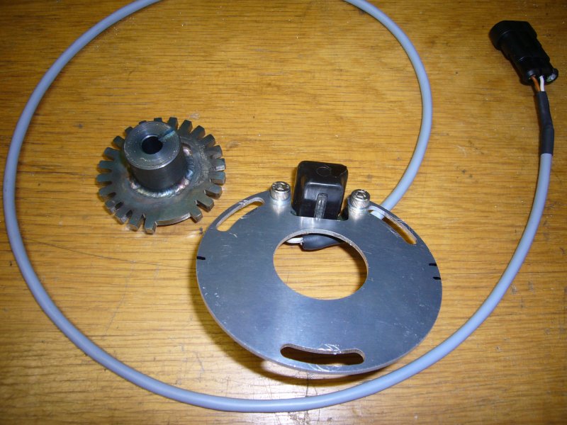
"The sensor is some generic VR pick-up and the wheel is laser cut from 5 mm thick mild steel. Mounting shaft is still under work. The wheel will be welded on the shaft. I hope to get this ready within next few days. Interesting to see if it works like expected. "
http://www.thegsresources.com/_forum/showpost.php?p=1859902&postcount=236

He's posted 17 times in this thread. Many dealt with fuel or charging issues.

In post 238, he said this:
http://www.thegsresources.com/_forum/showpost.php?p=1859910&postcount=238
"I have few spare pieces of those 24-2 wheels. I can sell one for quite reasonable money if you like. Or even complete trigger set once I have verified it works"

There was also a post about a 12-1 wheel not working on a bike, then the latest batch of posts.

Here are the facts I have gleaned:
1. Nowhere in there was there a tested setup offered for sale, or any price mentioned.
2. I've never seen a tooth graph for his 24-2 wheel. Is it better than the ones I had made? That is impossible to tell without two charts to look at.
3. I've learned what one member calls reasonable another calls being ripped off.
4. It's also worth noting he is in Finland, which while beneficial for members in that part of the world would add shipping costs to those in the US. The Pamco comes out of South Carolina. I paid for it Friday and had it Monday, for $6 shipping.
5. I said I'd link his info post on the index page so he can sell any extra units in the future based upon my project thread. If I was against his setup, I'd not do that.

BTW, while you're on page 1 (the index), look at the center linkage and ignition module info. It's from you. It has good photo info for how to do the linkage, and specific part #/application info for the modules. Easily repeatable. :)

I expect this will further upset you all, but I deal with facts. It's not my intention to upset anyone, but I look at projects as just that- can it be done with the original goal in mind? It says right up top on post #1 the the goal is to make it repeatable.

The goal of this project is to make a repeatable setup another can use. Please note the painstaking detail for things such as a fuse panel. I try and link everything I use so another reading this can click and go there without having to dig through pages of stuff. I'm also trying to add ballpark prices I pay.

I ran into a similar thing with the fuse panel where someone said I should have used "Brand X" (I forget the name) that had fewer circuits and cost like twice as much.
 
Last edited:
Yes you are correct, my mistake. Arttu offered you a 24-2 wheel setup. I have bought from Arttu & his prices are inexpensive & the part works. Finland is as far from me in England almost as S Carolina but we all have a reliable postal service. I have just bought a custom tip over module for my installation from Canada, post took less than a week.
Incidentally I also have a day job too in aerospace engineering & another 5 bikes to look after but I am not complaining.
Anyway rant over & let's put this behind us. I want to see your project finished so I can compare your final result to my own as both projects are very similar but we have approached them from different angles. Needless to say I think my way will be the best lol.
Having said that I think you may get yours finished first. We will see.
Nick
 
Back
Top