• Required reading for all forum users!!!

    Welcome!
    Register to access the full functionality of the GSResources forum. Until you register and activate your account you will not have full forum access, nor will you be able to post or reply to messages.

    A note to new registrants...
    All new forum registrations must be activated via email before you have full access to the forum.

    A Special Note about Email accounts!
    DO NOT SIGN UP USING hotmail, outlook, gmx, sbcglobal, att, bellsouth or email.com. They delete our forum signup emails.

    A note to old forum members...
    I receive numerous requests from people who can no longer log in because their accounts were deleted. As mentioned in the forum FAQ, user accounts are deleted if you haven't logged in for the past 6 months. If you can't log in, then create a new forum account. If you don't get an error message, then check your email account for an activation message. If you get a message stating that the email address is already in use, then your account still exists so follow the instructions in the forum FAQ for resetting your password.

    Have you forgotten your password or have a new email address? Then read the forum FAQ for details on how to reset it.

    Any email requests for "can't log in anymore" problems or "lost my password" problems will be deleted. Read the forum FAQ and follow the instructions there - that's what we have one for...

  • Returning Visitors

    If you are a returning visitor who never received your confirmation email, then odds are your email provider is blockinig emails from our server. The only thing that can be done to get around this is you will have to try creating another forum account using an email address from another domain.

    If you are a returning visitor to the forum and can't log in using your old forum name and password but used to be able to then chances are your account is deleted. Purges of the databases are done regularly. You will have to create a new forum account and you should be all set.

GS1000G mods- big bore and fuel injection

  • Thread starter Thread starter GS1000G Shopper
  • Start date Start date
Well I am glad you seem to understand all of that. Sounds complicated to me but I think I get the general idea.
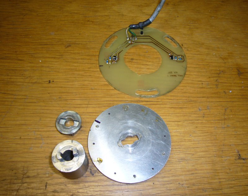
Regarding the advance/retard weights, I have tried to drill them but they are hardened steel. I think I would look at lock wiring them up, or maybe welding the moving sleeve to the shaft? If you want to buy something then have a look on eBay at this item 160907825773.
Pingel also sell the same http://www.pingelonline.com/billet_advance.htm
I did make a copy to use with my previous ignition system but it was a little tricky to get the dowels in the correct place.
 
The Microsquirt forum has a lot of crickets chirping. :(

Just saw your post, thanks for the link and eBay item, which is $32. $17 to ship a small piece of aluminum? I oppose that on principle, sell it for what you want, don't screw people with inflated shipping costs. The Pingel page won't load to show the price. I guess if you have to ask how much... :) I found a PDF link for their prices and it looks to be $53.05 plus shipping, so eBay is the better deal.

These do not appear to have a "tooth" on them so the pickup coil can read the crank position, so I presume you add old parts onto them?
 
Last edited:
I removed the advance unit & tried to keep it simple by bending in the arms that limit the weights moving out. One broke off, so I broke off the other one, ground them down, and welded the weights to the base. While cleaning the welds, I managed to nick the round part where the dowel goes, I'm not sure if this seals on the oil seal in the case or not. I may invest in one of the Pingel units, as I'm sure this part needs to be evenly balanced.

EDIT
Seems like the thing to do with this apart is to figure out how to add a 36-1 wheel in place of the advance unit using the pins on the billet part. I can't find one smaller than 4" in the USA, the link is a place in England that sells a 2.5" version. The next battle after that is to figure out how to mount a pickup using the OEM mounts.
 
Last edited:
No it doesn't run on the seal. It sits inside the recess in the crank. The crank runs on the seal. It should be fine. The pingel item is cool though but i reckon get the thing running first.
 
Thanks for the info. I'm concerned about centrifugal imbalance. I don't think it will come apart, but I'm not sure I removed equal amounts of metal, or added equal amounts while welding.
 
Ref the problem with the 36-1 trigger, if you look at the picture I posted you may be able to see how I did it. Its easiest to make a whole new mount with a cutout at the rear to locate on the dowel in the crank & a flange on the top to bolt the wheel to. You will also need a new baseplate as the pickup needs to be moved outboard as the new trigger is a larger diameter. It all work & it was easy for me to make as I have the equipment at home. As I am in England getting the wheel was easy too for a change. If you want more pictures let me know & I will take it apart tomorrow & post some. Nick
 
I have a program called E Machine Shop. It's a lot of fun, I designed some pistons (OEM had been discontinued) for some ST1100 brake calipers. I used it to design a 36-1 wheel that is 2.5" in diameter and would bolt on in place of the advance unit. I sized the notch, but it would need proper alignment. Also, the distance between the pickups is only 1.2", so the wheel would likely need to be much smaller. The case cover for this part of the engine is 4.9" in diameter. I'm going to experiment with making a smaller diameter wheel, with fewer teeth.

Here are some pics of what I ended up with. The cost would be prohibitive for just one.


One other alternative would be to machine a spacer with a notch in it and a center hole, and then bolt a small trigger wheel to it. There is not much room to work with things here, the diameter of the end with the notch is .95", so really small screws would be needed to bolt a 1.2" diameter wheel into place, and then it would need to be perfectly centered. I think a one piece as I've laid out would be better.

Here is a pic with the wheel scaled to 1.20" diameter:

 
Nice looking models. I would suggest making it in 2 parts. Make the centre boss with a shoulder & the hole in the trigger sized for an interference fit. Align it fairly closely, heat & freeze & press together. It won't move. Any adjustment can be made via the slotted holes in the baseplate & the offset in tuner studio. The teeth on most triggers are more of a squared off shape rather than like gear teeth. Would be easy to make with a dividing head & mill with a slitting saw or a small diameter cutter. Or laser cut if you know someone.
You would need to make the pickup slightly adjustable too as the gap between the tooth & the sensor was critical on my bike. Bit of trial & error & logging fixed it.
Nick
 
It's a challenge to design. I have to start with a gear in E Machine shop, or use a dxf file I found for a 36-1 trigger that is huge. I may be able to have more luck with fewer teeth on the wheel. I found a low cost pickup that could be installed in a bolt and filled with epoxy. The cost estimate I got for 1 trigger wheel was around $165. I know there is no market for these, so I will stick with my welded unit for now.
 
I'm wondering what would happen if I just used the 1-4 pickup with the VR1 input? My spark outputs are tied together in Tuner Studio no matter what input setting I use. I have to wonder how would the MS know when to fire 2-3? A 36-1 wheel only senses the engine at one location, as the single tooth OEM pickup does.

This part is far more complicated than I ever thought it would be.

That is what I use with the 36-1 trigger. You programme the ms so that it counts the teeth from the gap. It therefore knows how many degrees away from that position the firing point is for 1 & 4 so it then fires 2 & 3 180 degrees later. This all well documented in the manuals for ms & ms extra. I believe that the greater the number of teeth the better the timing accuracy as when accelerating the time between pulses will vary so the teeth allow more accurate prediction. That is my understanding. Does this make any sense. I think by using the OE dual trigger setup with only 1 tooth there will be very imprecise prediction for advance.
 
I'm not even getting any backfiring now, so it's getting worse not better. I have not tried the single pickup. What I'll likely do is just unbolt the 2-3 pickup and try to start it w/o the side cover on.

EDIT
Looking at the stock pickup/advance unit, the slot in the part that fits on the crank is 90 degrees opposed to the tooth. The GS uses a 17 degree BTDC setting at idle (< 1500 RPM), so I think I can make heads & tails of this.

I'm about ready to ditch the B&G 3.78, the Microsquirt forum is a ghost town. I had one reply to several posts, and it chastised me for pointing out a link did not work on a thread I "resurrected" (it was a pinned/sticky post, so I figured it was one meant to be used for reference). Apparently I'm not the only one that has had this experience:
http://xjbikes.com/Forums/viewtopic/p=370987.html
A frustrated guy said:
I need some help with my setup and the microsquirt forums suck!! No participation on there.
 
Last edited:
I'm not even getting any backfiring now, so it's getting worse not better. I have not tried the single pickup. What I'll likely do is just unbolt the 2-3 pickup and try to start it w/o the side cover on.

EDIT
Looking at the stock pickup/advance unit, the slot in the part that fits on the crank is 90 degrees opposed to the tooth. The GS uses a 17 degree BTDC setting at idle (< 1500 RPM), so I think I can make heads & tails of this.

I'm about ready to ditch the B&G 3.78, the Microsquirt forum is a ghost town. I had one reply to several posts, and it chastised me for pointing out a link did not work on a thread I "resurrected" (it was a pinned/sticky post, so I figured it was one meant to be used for reference). Apparently I'm not the only one that has had this experience:
http://xjbikes.com/Forums/viewtopic/p=370987.html
I expect I have all these problems to come. As yet I have not completed the mechanical side of the injection parts. I concentrated on getting the ignition side of things to work before I removed the carbs just to be able to isolate any future problems I may have. I guess its too late for you to try this now.
 
Some food for thought for trigger wheel implementation.

Here is the setup that I have been using by this far.
crank_trig.jpg


It uses two hall sensors, the trigger wheel is made of aluminum and there are magnets mounted in the wheel to trigger the sensors.

hall_trig_parts.jpg


The wheel is mounted on the crank with a short intermediate shaft. The mounting bolt clamps the wheel on the shaft and original 19 mm hexagon "nut" is also included to provide a way to rotate the crank with a wrench.

Recently I switched to MS3 ECU and to sequential injection / ignition with camshaft sensor. It seems this setup would benefit from better crank trigger resolution so now I'm making a new trigger arrangement.

24_2_parts.jpg


The sensor is some generic VR pick-up and the wheel is laser cut from 5 mm thick mild steel. Mounting shaft is still under work. The wheel will be welded on the shaft. I hope to get this ready within next few days. Interesting to see if it works like expected.
 
Thanks. All of my E Machine designs be they 36, 24, or 12 teeth do not pass internal validation, meaning they cannot make the part as designed.

I think I can export the best file and have a 1-piece part made at another machine shop. I have the dimensions needed.

In more bad news, I tried the single pickup and still no start. I detected a small fuel leak under the throttle bodies so I will pull them and see where the fuel is leaking. I can also look at the injectors and make sure they are fueling while I have the TBs off the bike.
 
I have few spare pieces of those 24-2 wheels. I can sell one for quite reasonable money if you like. Or even complete trigger set once I have verified it works ;)
 
Let me check into a few other options first. Thanks for the offer.
 
I have made a 2-part trigger wheel setup that shows as being machinable and will bolt on. I looked into the press-fit, but adding to the rear of the wheel makes it difficult if not impossible to machine.

Part 1 is a spacer that takes the place of the advance assembly. It has a notch in the bottom so it fits in to the crank opening. The top has 2x 8-32 holes in it so the wheel can be bolted on.


Part 2 is the 12-1 trigger wheel. I added 4 sets of holes so it can be mounted in various positions. Coupled with an adjustable Hall sensor, this would allow for a great deal of timing variation.
 
Last edited:
I pulled the throttle bodies today and it looks like the fuel leak was most likely the joint where I had a brass 1/8 pipe fitting in place, but a couple of the small injector o-rings looked bad also. I found some 3/8 aluminum fuel line would fit in where I had threaded for 1/8 pipe, so plan B is to cut a short section, rough up the ends, and use some JB Weld to reassemble it. I can then clamp it in place so it sets straight.

EDIT
The little O-rings are $6.06 each! Time for McMaster.com again. I can likely get 25 Viton O-rings for that price.

UPDATE
I tired several sizes of o-rings that were not a good fit. The size needed based on measuring the OEM ones is a 7.5mm ID x 2.0mm thickness, which yields an 11.5mm OD. McMaster does not sell these, but they do sell a 7.8 x 1.9 that yields an 11.6 OD. A bag of 10 in Viton is about $6.
 
Last edited:
Back
Top