• Required reading for all forum users!!!

    Welcome!
    Register to access the full functionality of the GSResources forum. Until you register and activate your account you will not have full forum access, nor will you be able to post or reply to messages.

    A note to new registrants...
    All new forum registrations must be activated via email before you have full access to the forum.

    A Special Note about Email accounts!
    DO NOT SIGN UP USING hotmail, outlook, gmx, sbcglobal, att, bellsouth or email.com. They delete our forum signup emails.

    A note to old forum members...
    I receive numerous requests from people who can no longer log in because their accounts were deleted. As mentioned in the forum FAQ, user accounts are deleted if you haven't logged in for the past 6 months. If you can't log in, then create a new forum account. If you don't get an error message, then check your email account for an activation message. If you get a message stating that the email address is already in use, then your account still exists so follow the instructions in the forum FAQ for resetting your password.

    Have you forgotten your password or have a new email address? Then read the forum FAQ for details on how to reset it.

    Any email requests for "can't log in anymore" problems or "lost my password" problems will be deleted. Read the forum FAQ and follow the instructions there - that's what we have one for...

  • Returning Visitors

    If you are a returning visitor who never received your confirmation email, then odds are your email provider is blockinig emails from our server. The only thing that can be done to get around this is you will have to try creating another forum account using an email address from another domain.

    If you are a returning visitor to the forum and can't log in using your old forum name and password but used to be able to then chances are your account is deleted. Purges of the databases are done regularly. You will have to create a new forum account and you should be all set.

GS550LX Engine rebuild dilemma

  • Thread starter Thread starter neeko
  • Start date Start date
N

neeko

Guest
I currently own a 1981 GS550LX in which I'm currently rebuilding the engine for.

All has gone smooth except for the fact that I broke 3 bolts off the cam cover (which required drilling BTW and after 2 successful extracts, the third one decided to not come out at all. In the end, I had a big missing piece off the cover)

Other notable moments:
-Dropping c-clip down into crank
-Dropping screw into transmission
-ACCIDENTALLY unscrewing of cylinder stud.( The nut securing it was covered in surface rust. After 2 nights of soaking I guess it worked itself all the way to the crank case portion as well. Now the damn thing is out and I don't know how many lbs to torque it back in at.)
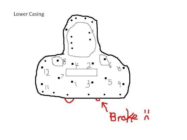
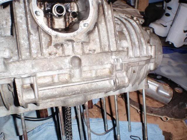
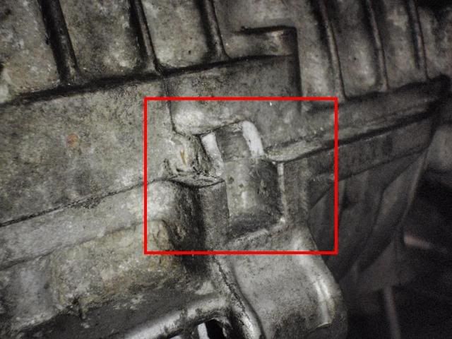
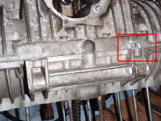
-Breaking a piece of engine (There are two points at the front of the engine above the oil filter. On the right side is the beefy point where on the left side is the less beefy point. In hopes of securing a bolt and nut in and then tightening it to creation an expansion in hopes of trying to crack the crank halves together; the engine mount decided to snap instead. &@#%!@^# ensued.)

My current dilemma,

I can't for the life of me get the Alternator magnet off the crank. The manual says to utilize swingarm bolt and use free sliding weight to act as impact hammer. Well, I just about tried everything plus somemore, but the damn thing only budged about 1cm. Removal of this part is not necessary so I just left it there atm.

I can't seem to get the crankcase halves to separate. The manual states to rest engine upside down on cylinder studs and remove all the 12mm bolts in sequence followed by the 10mm bolts on the lower. What the manual failed to mention as well was that there is an extra 10mm bolt next to the oil sensor that also keeps the two halves together. As far as I can tell, everything is off but I still can't get the 2 halves to open. Are there any tips and tricks?

Much thanks to any tips or advice to assist in removal!

Thanks
 
There are 3 jacking points on the crankcase halves. Use these to put pressure on the halves to separate them. I hope you haven't broken these off. Check your parts manual which will show all the bolts to come out. Make sure they are all out before you start jacking the halves apart.

BTW the halves are held together with 6mm and 8mm bolts.
 
I've just checked. There are seven bolts inside the sump area. 2 x 8mm and 5 x 6mm. Make sure these are all out.

Check out this blown up diagram of the bottom of the '77 GS550 motor. Count up the bolts and make sure they are all accounted for. Your motor should be the same as this one as it is a 8-valve motor.

Twenty nine bolts in total by my count -- make sure they are all out.
 
Last edited:
I am just a little confused and would appreciate some clarification about the whole project.
... and after 2 successful extracts, the third one decided to not come out at all. In the end, I had a big missing piece off the cover ...
Just not sure how a stuck bolt results in a "big missing piece off the cover". :-k


Now the damn thing is out and I don't know how many lbs to torque it back in at.
You are doing this without a service manual? :eek:
I ask this because ALL of the service manuals have torque value tables.


I can't for the life of me get the Alternator magnet off the crank. ... Removal of this part is not necessary so I just left it there atm.
If it's not necessary to remove it, why are you trying?

I am also not understanding "atm".


I can't seem to get the crankcase halves to separate.
I understand the need to retrieve the screw you dropped into the transmission, but don't understand how it got dropped into the transmission if you don't have it open yet.

What started all this and why do you feel the engine needs to be rebuilt? Just wondering if it's all necessary or you might be going overboard.

.
 
In addition to the 29 bolts shown in the diagram below, there is also one small bolt which comes in from above, plus a nut holding a short stud by the output shaft. Those must also be removed to get the crankcase halves apart.

To +1 Steve, all of this info is in the factory service manual - which may be freely downloaded from BassCliff's site. The torque on the head nut will be the same whether you are tightening the nut onto the stud or the stud into the upper crank half (the clamping force does not change). Apparently you do have the manual as you have read the rotor removal instructions.

I also second steve that I'm not sure WHY you're going through this exercise - just for your own education and experience? I had to remove the rotor, but that's because I was replacing a twisted crank with a used crank which came with no rotor. It is a pain, and I managed to damage the threads on my old crank (fortunately it was being replaced anyway). Unless you're trying to replace the bearings for fun there's really no reason to pull the rotor. If you must, put a slender rod of some kind (cut threaded rod, maybe an allen-head bolt) down in the rotor bolt hole, ensuring that you have about 0.5 to 1 cm of thread, then put the swingarm bolt back in. I also suggest you wrap the rod/bolt threads in tape so you don't damage the threads on the rotor or the crank. Or just go find/buy a bolt with the same thread dia/pitch as the swingarm bolt (16Mx1.0? not sure) but with a longer threaded section.

If you're just trying to retrieve parts out of the case, was removing the oil pan not enough?

And Steve - "ATM" is "At The Moment" in cyber-speak :)
 
And Steve - "ATM" is "At The Moment" in cyber-speak :)
Thanks, I just could not picture what an Automated Teller Machine had to to with leaving his rotor in place.
I'm still relatively new to "texting", so I don't know and don't intend to use all the shortcuts.

Most of us are using full-size keyboards that have all the letters, why not use them?

I know there are some abbreviations that tend to get crude, so it's best to not spell them out,
but, quite frankly, you can probably get by without that expression all together.

.
 
In addition to the 29 bolts shown in the diagram below, there is also one small bolt which comes in from above, plus a nut holding a short stud by the output shaft. Those must also be removed to get the crankcase halves apart. :)

OOPS!! I forgot the two top attachments, one bolt and one nut either side of the transmission output shaft as MIKE has pointed out. That makes 31 in total.

When I split my crankcases I had to drill the heads off three of the 8mm bolts as they had become completely rounded off when trying to get them out. And before you ask, YES, I was using a quality Sidchrome socket set. The bolts would just not let go. After splitting the cased the remains of the bolts unscrewed easily with finger pressure. No spanners required.
 
Bits in engine story.....

I bought a junkyard gs1100G head to replace the head on my GS1000G, when I got it home and started tearing it down, one valve was held open by a hose clamp a PO had dropped down a spark plug hole. I imagine this is how it wound up being a junkyard head.
 
I noticed that you guys mentioned the 6 and 8mm bolts. Even my manual mentions that; but the fact is that the only sockets that fit were 10mm and 12mm sockets. Won't that make them 10 and 12mm bolts instead?

Hmmm I might of missed one screw. After redoing my count, I ended up with 30; 17 of them being 10mm bolts whilst the other 13 being the numeric 12mm bolts.

I really appreciate everyone's input!

The main reason I decided to rebuild the motor is because of the 12x,xxx miles on it already and that the PO decided to keep it outside next to a barn under a worn down tarp since Sept of 1990.

BassCliff, I'll snap some pictures of the cover once I bring it back home. I left it out at my uncle's shop AT THE MOMENT and will be bringing it back this weekend or the next.

As for the jacking points; I don't have the original FSM. I'm following my Haynes Owners Workshop Manual for all the steps and I've already noticed a few missed bolts already that weren't mentioned in the manual itself.

Originally, I thought to myself; if the damn heads and the cylinders were A-OK I would just leave it at that. Then come removing the circlip from the piston and down it goes into the crank housing (OOPS on my part) and another whilst removing the 10mm bolt section on the lower crank. I once again drop it within the transmission and lose it inside.

Heres a rough drawing of the bolts I removed from the lower half minus the one LONG 10mm bolt I removed from the top half by the oil sensor.

LowerCasing-1.jpg


Picture017-2.jpg


Picture018-2.jpg


Picture020-1.jpg
 
Thanks, I just could not picture what an Automated Teller Machine had to to with leaving his rotor in place.
I'm still relatively new to "texting", so I don't know and don't intend to use all the shortcuts.

Most of us are using full-size keyboards that have all the letters, why not use them?

I know there are some abbreviations that tend to get crude, so it's best to not spell them out,
but, quite frankly, you can probably get by without that expression all together.

.

I LOL'd (Laugh Out Loud) so hard when I pictured your confusion in my head. Because of that I have soda all over my notes.
 
Did you remove the plates behind the clutch basket that bridge the crankcase halfs?
 
I noticed that you guys mentioned the 6 and 8mm bolts. Even my manual mentions that; but the fact is that the only sockets that fit were 10mm and 12mm sockets. Won't that make them 10 and 12mm bolts instead?
Bolts are not measured by the size of the wrench necessary to move them. They are measured by the diameter of the stem before the threads are cut. What you are calling "10mm bolts" are actually "6mm bolts" because the threaded portion is 6mm across. Your "12mm bolts" are actually "8mm bolts".

To illustrate some confusion that could arise, the 8mm bolts that we find on our bikes and many (most?) "Japanese" cars use a 12mm wrench. If you go to Auto Zone or Ace Hardware to get an 8mm bolt, it will require a 13mm wrench. Frustrating, but that's the way it is.

.
 
As mentioned, the FSM is available in electronic format from BassCliff's site:

http://members.dslextreme.com/users/bikecliff/

GS550 ('77-'82) Service Manual (72MB)

There should be 30 bolts. I hope you are keeping track of where they go as they're different lengths! 29 on the bottom, and one 6mm bolt on the top. There is also the nut I mentioned by the output sprocket. Plus you have a seal retainer on the output shaft and a bearing retainer under the clutch basket. Those bridge both halves of the crank case. The bearing retainer usually requires the use of an impact driver to get the three screws out. The bond they put between the cases is pretty good stuff, so don't expect the cases to come apart easily after all the fasteners are out!

That damaged part you highlighted in your pics is one of the jacking points (I only recall two of them - one in the back of the case and one in the front - though someone else said three). They're mightly useful for splitting the cases, but at least won't present a problem w/r/t leaks or engine mounting when back together. Those case halves are matched sets, so try not to break anything else on them or you'll have to buy BOTH halves of the case used (or maybe just a whole used motor). You still have a jacking point in the back to help get the case halves apart.

As Steve mentioned, the bolt "size" is the nominal shaft diameter. Though the head size is more useful to the guy with the wrench, that nominal shaft diameter is more important from a design and part replacement perspective!

Did the PO mention if there were any problems before he parked it? There's not a whole lot that can be done down in the crank case. I guess you can examine parts are see if anything is obviously amiss, but it probably would have been more fruitful to get the carbs rebuilt and get the motor running. It's hard to look at the tranny gears and see that you'll have a problem with it popping out of 2nd, but you'll know it when you drive it! Though, it is a nice learning experience if you've not delved into motors or trannies too much and costs little more than a tube of threebond and an o-ring.

Good luck to ya.
 
Hey Mike, Steve, Nessism and everyone else,

I would like to thank you all for the information you contributed and for helping me each step of the way.

About a week ago I successfully seperated both halves of the crank case after removing that hidden SOB nut by the output sprocket.

I've already cleaned all the parts and after cleaning the work space I'll start the reassembly.

I was just wondering; for all the engine builders out there; is there a specific brand of sealant that I should be using for the crank case halves or the autozone junk will hold up?

I also acquired a 1979 gs550 kickstart assembly that I'm looking to install into this case. The case already has the slot and screw holes for it so I'd figured why the hell not.

Seeing how this is a electric start bike; will there be any problems with installing a manual kickstart even though its a drop in fit?

Thanks in advance!
 
Threebond 1194 or 1207 is the stuff. You can use some Ultra Silicone but the Threebond stuff is the real deal.
 
Yeah, I used Threebond 1194. Honda, Yamaha, and Suzuki dealers will probably stock an equivalent product if you don't want to wait for (or pay for) shipping for one tube of bond - though it'll probably cost you an extra buck or two. Beware anything from AAP or any other parts store unless it's made specifically for this purpose.

I haven't tried it myself, but I didn't think a kick-starter could be installed on the 80+ GS550 motors. There appears to be a casting for it inside the case, but I remember reading somewhere here that there was some other difference that meant it couldn't be done in the newer cases - even with the clutch cover and internals from a 77-79.

Even if I'm way off in my memory, you probably want to check the teeth on the starting pawl. The first couple years of GS550 used straight teeth on the crank and clutch basket, but they went to a slanted design later. Had to watch that when I was buying a used crank...
 
Lucky for me; I stopped by a old school autoshop during my lunch break and low and behold they carried the threebond stuff so thats off the list now.

I did notice that the contact gear teeth on the kickstarter was straight. I'll have to check when I get home
 
Even if I'm way off in my memory, you probably want to check the teeth on the starting pawl. The first couple years of GS550 used straight teeth on the crank and clutch basket, but they went to a slanted design later. Had to watch that when I was buying a used crank...

With due respect the teeth on the starting pawl has nothing to do with the teeth on the crank gear and clutch basket.

When the kickstart is operated the shaft engages the starter pawl through a rachet system which in then turns the large 1st gear on the drive shaft which turns it's mating gear which is a casting on the countershaft and the clutch which is on the end of this shaft rotates the crank via the teeth on the clutch basket.

The starter pawl gear does not come into contact with the clutch basket gear or the crank gear at any time, so it does not matter whether these two gear are cut straight or helical.

Hope that makes sense, I know what I mean, others might not.

A few pics for reference.

S3010011.jpg


S3010014.jpg


S3010015.jpg


Some of the problems I had getting the screws out.

S3010028.jpg
 
Last edited:
Sorry for the lack of updates, but I was recently giving the opportunity to work more hours so that took precedence over the engine rebuild.

Following my last update; I got myself a nice stick of threebond 1194 and couldn't wait to get home and reassemble the halves.

Well since I got back home and fitted the parts together with the kick starter shaft assembly; I noticed something wasn't looking right.

First off, the kick starter dropped in like nothing and everything fitted as if it was originally included. The sad part is that I'm missing the guide plate that mounts onto the crankcase behind the shaft.

You could see the plate in one of Suzuki-Don's picture sitting behind the shaft secured by two phillips screws and that is the part that I'm missing.

After a quick search on the net, it is safe to assume that the part is discontinued and that no retailer/reseller is stocking it.

Cycle-parts.com has one thats highlighter in green (assuming they have maybe one in stock) so I just placed my order with them. If its out of stock they will email me back and won't charge me or so they say.

But as of this point; the 1979 Shaft and Plate WILL FIT a 1981 GS550L! Which means YES YOU CAN DUMP THE EARLIER YEAR KICKSTARTER INTO THIS ENGINE. BUT IF IT WORKS OR NOT IS STILL YET TO BE TESTED.

My friend managed to drown my camera on his trip so I am now camera-less. However, I was promised a new camera so I will snap shots once I get it.

Suzuki-Don, do you have pictures of the kickstarter shaft with the spring attached? I'm looking at my assembly and want to make sure that I have the spring secured correctly.

Thanks!
 
Neeko, sorry I must have missed this post somehow. Been busy with my own project. Been spending too much time in the workshop and not enough on the FORUM it seems.

I am including all the pics I have on the kickstart removal replacement.

BTW the kickstart gear does mesh with the large driven first gear in the transmission at all times.


m_S3010017.jpg


m_S3010016.jpg


m_S3010015.jpg


m_S3010014.jpg


m_S3010013.jpg


m_S3010012.jpg


m_S3010011.jpg


m_S3010010.jpg


m_S3010009.jpg


m_S3010008.jpg
 
Last edited:
Back
Top