G
Guest
Guest
Lever
Lever
I like that!!! A nice, big easy to see and grad lever. What more could you ask for?
G
Lever
I like that!!! A nice, big easy to see and grad lever. What more could you ask for?
G
Required reading for all forum users!!!
Welcome!
Register to access the full functionality of the GSResources forum. Until you register and activate your account you will not have full forum access, nor will you be able to post or reply to messages.
A note to new registrants...
All new forum registrations must be activated via email before you have full access to the forum.
A Special Note about Email accounts!
DO NOT SIGN UP USING hotmail, outlook, gmx, sbcglobal, att, bellsouth or email.com. They delete our forum signup emails.
A note to old forum members...
I receive numerous requests from people who can no longer log in because their accounts were deleted. As mentioned in the forum FAQ, user accounts are deleted if you haven't logged in for the past 6 months. If you can't log in, then create a new forum account. If you don't get an error message, then check your email account for an activation message. If you get a message stating that the email address is already in use, then your account still exists so follow the instructions in the forum FAQ for resetting your password.
Have you forgotten your password or have a new email address? Then read the forum FAQ for details on how to reset it.
Any email requests for "can't log in anymore" problems or "lost my password" problems will be deleted. Read the forum FAQ and follow the instructions there - that's what we have one for...
If you are a returning visitor who never received your confirmation email, then odds are your email provider is blockinig emails from our server. The only thing that can be done to get around this is you will have to try creating another forum account using an email address from another domain.
If you are a returning visitor to the forum and can't log in using your old forum name and password but used to be able to then chances are your account is deleted. Purges of the databases are done regularly. You will have to create a new forum account and you should be all set.
At least for my 1166, I find that keeping the battery charged up significantly reduces the kick back. When the battery is low it is much more prevelant.
")

All very good questions John ;I think you do understand it.I looked at your schematic for option 5 but I'm not sure I understand it ?
Are you really taking the ground connection of the CDI to the + 12V through the starter switch ?
Isn't the whole CDI box connected to the ground connection ?
When you release the starter switch you are grounding the CDI box through the starter solenoid thus allowing the sparks to be produced.
So in fact you are counting on the inertia of the crankshaft to keep rotating the engine until a spark ignites the engine.
What's the voltage drop across the solenoid ?
Doesn't that weaken the spark ?
") The solenoid is 3-4 ohms and the coils are 3-4 ohms so that would cut the coil voltage in 1/2 if the coils actually grounded through the B/W coming from the ignitor. I cant help but think that would be noticeable. So my guess is that the B/W is only a signal ground and the rest of the coil current actually goes through the case. The signal ground is probably in series with bias circuits that are in the 10's of Kohms and so 3-4 ohms is nothing.
The solenoid is 3-4 ohms and the coils are 3-4 ohms so that would cut the coil voltage in 1/2 if the coils actually grounded through the B/W coming from the ignitor. I cant help but think that would be noticeable. So my guess is that the B/W is only a signal ground and the rest of the coil current actually goes through the case. The signal ground is probably in series with bias circuits that are in the 10's of Kohms and so 3-4 ohms is nothing.It's definitely not a very orthodox way of doing things but if it works why not ?All very good questions John ;I think you do understand it.
This is basically another simpler way of implementing the OLD Option #3 in the write up. inhibiting spark while cranking and yes that relies on the inertia to keep the engine running till you get that first spark and then VROOM. This method uses no relays where as the older design used two relays.
I have to confess of not knowing exactly why this works. As I have posted a member here who upon installing a SSPB with headlamp cutout suspected that the SSPB had something to do with cutting out spark. As it turned out his bike ad been wired this way every since he had owned it and he had never realized the behavior before the SSPB install. Presumably checking out the headlamp cutout is what focused his attention to realize the PO modifications. Based on that I would say it is a viable approach for some bikes using the OEM ignitor. I can not say I strongly recommend it, but it is worth a shot if you are so inclined. The headlamp cutout is probably much more universal solution.
With respect to the grounds, again I don't know other than it was said to work without any notice of degradation.
This would not work with a Dyna -S for example as the Dyna-S ground through to the engine from the ignition timing plate. It would not work with points as they do the same. Perhaps a Dyna-2000 or such would have a similar working.
I would however, strongly recommend the headlamp cutout and even perhaps the use of LED's for all signals and probably LED for the headlamp. This all helps provide more amperage to spin the motor faster during cranking.
In the end, I went with modification #2.
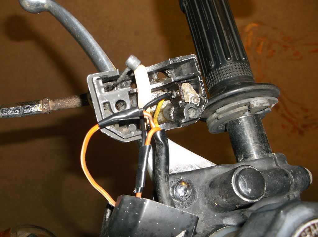
The way I did it consisted in simply switching the White/Orange leads at the plug level coming out of the right switch assy.
The W/O lead with an orange plastic band brings the switched +12V to the "engine stop" switch before going to the "starter switch".
By switching the leads as described the W/O lead with the orange plastic band now feeds directly the "starter switch" and the "engine stop" switch.
I don't know if this will work on US models?
option #2.
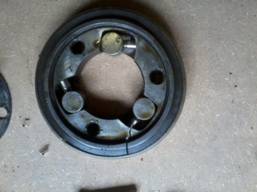
after doing this to two starter clutches: