For sure..just was thinking about the getting to see the pathways and numbers on the components to reference off of..thats my thinking here.
-
Required reading for all forum users!!!
Welcome!
Register to access the full functionality of the GSResources forum. Until you register and activate your account you will not have full forum access, nor will you be able to post or reply to messages.A note to new registrants...
All new forum registrations must be activated via email before you have full access to the forum.A Special Note about Email accounts!
DO NOT SIGN UP USING hotmail, outlook, gmx, sbcglobal, att, bellsouth or email.com. They delete our forum signup emails.A note to old forum members...
I receive numerous requests from people who can no longer log in because their accounts were deleted. As mentioned in the forum FAQ, user accounts are deleted if you haven't logged in for the past 6 months. If you can't log in, then create a new forum account. If you don't get an error message, then check your email account for an activation message. If you get a message stating that the email address is already in use, then your account still exists so follow the instructions in the forum FAQ for resetting your password.Have you forgotten your password or have a new email address? Then read the forum FAQ for details on how to reset it.
Any email requests for "can't log in anymore" problems or "lost my password" problems will be deleted. Read the forum FAQ and follow the instructions there - that's what we have one for...
-
Returning Visitors
If you are a returning visitor who never received your confirmation email, then odds are your email provider is blockinig emails from our server. The only thing that can be done to get around this is you will have to try creating another forum account using an email address from another domain.
If you are a returning visitor to the forum and can't log in using your old forum name and password but used to be able to then chances are your account is deleted. Purges of the databases are done regularly. You will have to create a new forum account and you should be all set.
You are using an out of date browser. It may not display this or other websites correctly.
You should upgrade or use an alternative browser.
You should upgrade or use an alternative browser.
This problem keeps eating at me.
So far I'm thinking of using a 556 (dual 555) timer in bistable mode to operate the relays and using a second 555 as a coundown timer when reaching a speed of 15 miles per hour. Then using a lm2907 as an over speed latch to start the 555 timer. Possibly a nand gate used so you can't operate both signals at once.
Any comments?
Boy, you're really aiming at an elegant solution. Mine has all the subtlety and sophistication of a ballbat -- almost insultingly primitive.
A pair of PICAXE's -- one is dedicated to watching the speedo reed switch and counting. The other handles everything else, which includes bar controls and the actual flashing. Output is to a pair of SPDT relays, one for left and one for right, with a simple Op-amp relay driver (like a UL2003) handling the relay coils. Two microcontrollers because the very instruction I need -- COUNT -- hogs a single unit down.
(Current PICAXEs provide a simulated "parallel processing" feature. OK, it's a polling routine, but who cares? It's great for programmers who are either unsophisticated or lazy, or both. Hey, I'm comfortable with either! But that 'COUNT' command screws up my flash rate. Can't have that!).
I'll be using the bar control from a '79. I have one that's almost new. All momentary switches (for the signals, of course. I'll have to adapt the switches for Hi/Lo beam and horn. No big deal there).
The relays will be socketed and mounted external to the 'box', which can now be really compact -- since there's almost no guts! Socketed relays mean that they can be replaced easily and quickly. I've found Bosch (which no longer makes relays!) on eBay for about four bucks a copy.
My concerns are of robustness (is that a word?) and maybe switch bounce. Other than that, the possibilities are endless. I need a robust unit because I haven't been able to figure out a "limp-home" mode for this. Either it works, or you have no signals (other than your hands...).
I'm also a bit concerned about power conditioning, but probably don't need to be. I'm planning on something really basic like an LM7805 linear regulator to feed the processors and an LM7812 to feed the relays. Protect it with a cap. Maybe a zener, but I'm not sure what to use there.
I should have this operational by early May or so.
R
rodman101
Guest
this all seems very complicated, what exactly is wrong with the two latching relays schematic, other than self canceling signals, and no colors to the schematic lol, hopefully not a stupid question, i just prefer works as opposed to not working
Mr Barr, I don't know if mine is all that elegant of a solution or not.
One of the considerations I had when I thought of making a replacement TSCU, was to make it from commonly available parts driving a pair of relays, only because I don't care to add learning a programming language to the things I already have on my plate.
I started out with the idea of using a pair of two coil SR relays to direct the current to the flashers and adding a means of 'time out' signal cancellation in addition to the cancel button. That evolved into using a bistable flip flop circuit to drive a pair of replaceable automotive SPST relays in sockets for ease of servicing as you have indicated you are doing with yours. One of the things on tomorrows agenda is to measure the coil current needed to operate the relays I already have on hand and see If I need to add a driver circuit or just go ahead and find a relay within the 555's requirements.
I'll 'probably' throw in a dedicated means of voltage regulation, but I'll make the decision after I see how much trash on the line those components can handle.
I have to admit, during the process of figuring a solution to this thing, a ?P was starting to look like the easiest way around it.
T
TheCafeKid
Guest
Orrrrrrrrr
You could buy a simple $7 flasher relay and remember to turn off your damn signals on your own")
I've had GSes with the self canceling feature. Some worked, some didnt. I found them annoying, particularly when one has to restart the timer in a long left turn que. I just did it my damn self so I knew they were on, or off....
Much simpler than fancy gizmos. Call me old fashioned I guess.
You could buy a simple $7 flasher relay and remember to turn off your damn signals on your own
I've had GSes with the self canceling feature. Some worked, some didnt. I found them annoying, particularly when one has to restart the timer in a long left turn que. I just did it my damn self so I knew they were on, or off....
Much simpler than fancy gizmos. Call me old fashioned I guess.
Josh, on the earlier model TSCU's with the factory provided turn signal switch it isn't quite that simple.
The early model turn signal switch has momentary contacts so you would need to hold the switch in the right or left turn position while its flashing, or remove the centering spring so it will not return to center when you release the knob AND rewire to eliminate the TSCU. They are nothing like the 80~up units.
The early model turn signal switch has momentary contacts so you would need to hold the switch in the right or left turn position while its flashing, or remove the centering spring so it will not return to center when you release the knob AND rewire to eliminate the TSCU. They are nothing like the 80~up units.
Nothing wrong with using the two latching relay method of getting around the problem.what exactly is wrong with the two latching relays schematic, other than self canceling signals, and no colors to the schematic...
Here's another solution -> http://www.thegsresources.com/_forum/showpost.php?p=1471473&postcount=21
AND, vee dough nee no steenking colors...
")
Mr Barr, Instead of using two picaxe's, what about these?
http://www.ti.com/tool/msp-exp430g2 at whopping $4.30!
http://www.ti.com/tool/ez430-f2013 $20.00
http://www.ti.com/tool/msp-exp430g2 at whopping $4.30!
http://www.ti.com/tool/ez430-f2013 $20.00
Orrrrrrrrr
You could buy a simple $7 flasher relay and remember to turn off your damn signals on your own
There's a trouble-maker in every crowd...
Dogma
Forum Sage
There's a trouble-maker in every crowd...
Not only that, a hypocrite too! As I've learned from much bitter experience, he doesn't cancel his turn signals, automatic or not. Just pokin' ya, Josh.
I don't actually disagree. The self-canceling system isn't really smart enough to take care of it's own job. You have to monitor the signals anyway, and for the wrong reasons. I wouldn't mind going without. I'm so trained to cancel turn signals that I do it in the car now, too.
S
sschering
Guest
Just wondering.. Why use a relay instead of a MOSFET like this that costs $1? http://www.sparkfun.com/products/10213
Headlght OK maybe a relay but everything else is only on for a short duration.
As for long lights I would think you could code the shut off timer to watch the speedo signal.. If the speedo stops sending halt the count and resume when the bike is moving again.
If making the PCB is an issue look at DorkbotPDX
http://dorkbotpdx.org/wiki/pcb_order
They do group PCB orders for $5 a square inch for 3 copies of the board.
If your board takes up 2 square inches you get 3 of them for $10 shipped..
That is etched, solder masked and silk screened..
They will work from Eagle cad file so you don't have to mess around with Gerber files.
Last edited:
In my case I thought it to be better to use relays just for ease of servicing on the road, but for a buck a piece I just may go ahead and plan to use them.Just wondering.. Why use a relay instead of a MOSFET like this that costs $1? http://www.sparkfun.com/products/10213
If making the PCB is an issue look at DorkbotPDX
http://dorkbotpdx.org/wiki/pcb_order
They do group PCB orders for $5 a square inch for 3 copies of the board.
If your board takes up 2 square inches you get 3 of them for $10 shipped..
That is etched, solder masked and silk screened..
And thanks for the link to Dorkbot, I'll need to find a cheep method of making up the pcb's as well. I had these folks bookmarked http://www.expresspcb.com/ExpressPCBHtm/Download.htm but hadn't started looking at other venders yet.
I think it would be best to reset the timer when it drops below a set speed threshold then returns back above it.If the speedo stops sending halt the count and resume when the bike is moving again.
Last edited:
R
rodman101
Guest
ok, 2 relays and remove a spring, sounds like a plan, now to figure out why i have no blinkers at all, course, that tscu may be why
These tscu's are known to go bad. I have 6 or 7 duds in my parts stash.
Does the turn signal switch on your bike have a spring loaded lever that you push down to cancel? A lever like this switch has?
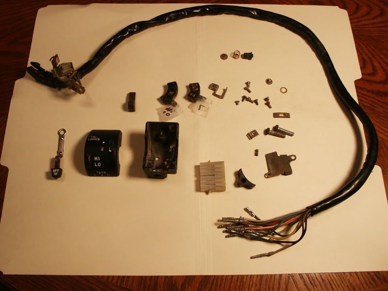
Does the turn signal switch on your bike have a spring loaded lever that you push down to cancel? A lever like this switch has?
R
rodman101
Guest
yes it has left right and down to cancel
so far all i know is that i have voltage accross the turn signal fuse, havent tested any further than that, oh, and good bulbs
so far all i know is that i have voltage accross the turn signal fuse, havent tested any further than that, oh, and good bulbs
S
sschering
Guest
BatchPCB is another option
http://batchpcb.com/index.php/Products
They have a $10 setup fee and $2.50 pr Sq inch
Shipping is extra with them but you can do a singe board order vs 3 with Dorkbot.
For a one off prototype I've had success with toner transfer from laser printed images on Dollar store photo paper onto copper clad from Radio shack.. 4x6 copper board at Radio shack is about $4.. the rest of the supplies is $5-$6
Print the circuit right from Eagle cad.. use big fat traces for easier transfer.
Layout tip. It's easier to etch a fine gap between traces then a fine trace with wide spacing. Toner transfer isn't perfect so go big
Iron the image onto the PCB with a clothes iron.. take your time.. press down, lift, move.. take you time and don't wiggle the iron or the image will smudge..
Give it 3-5 min total with the iron on high..
When done drop the board with the paper stuck to it into a dish of hot soapy water and let it soak.. The wet paper will fall apart easily leaving the top layer and toner stuck to the board.. just rub the paper off with your finger.. Any small breaks in the toner (or big) can be patched up with nail polish.
I etched the board using Vinegar and Hydrogen peroxide (mix 1:1 ) and a little bit of salt.. Don't go nuts with the salt.. They use calcium carbonate as an anti caking agent so adding a ton of salt just helps neutralize the vinegar. It took 12 hours to etch a 1oz clad board but it does work.
Failed toner transfer and post etching cleanup can be done with acetone.
Last edited:
Mr Barr, Instead of using two picaxe's, what about these?
http://www.ti.com/tool/msp-exp430g2 at whopping $4.30!
http://www.ti.com/tool/ez430-f2013 $20.00
If I spoke 'C', I might already be spending money on this...
R
rodman101
Guest
ok, call me stupid, but what exactly does this object do, not labeled, and its not connected, wires are taped off. dont know if this is the tscu or what, found that i do have voltage to the turn signal switch. and the turn signal switch contacts are working fine. oh, the object im refering to is the one between the flasher relay and the main fuse
im a glutton for punishment, but this thing is gettin rediculous, lol
im a glutton for punishment, but this thing is gettin rediculous, lol
Last edited:
Stupid.....
That was what you wanted someone to do correct?  (couldn't resist it!)
The item you are referring to looks like a voltage regulator, but it's hard to tell from your picture. Can you remove it and take a better picture of it?
***edit***
Your tscu is on the other side of the bike and looks like this ->
http://www.thegsresources.com/_forum/attachment.php?attachmentid=15157&d=1323394052
(couldn't resist it!)The item you are referring to looks like a voltage regulator, but it's hard to tell from your picture. Can you remove it and take a better picture of it?
***edit***
Your tscu is on the other side of the bike and looks like this ->
http://www.thegsresources.com/_forum/attachment.php?attachmentid=15157&d=1323394052
Last edited: