• Required reading for all forum users!!!

    Welcome!
    Register to access the full functionality of the GSResources forum. Until you register and activate your account you will not have full forum access, nor will you be able to post or reply to messages.

    A note to new registrants...
    All new forum registrations must be activated via email before you have full access to the forum.

    A Special Note about Email accounts!
    DO NOT SIGN UP USING hotmail, outlook, gmx, sbcglobal, att, bellsouth or email.com. They delete our forum signup emails.

    A note to old forum members...
    I receive numerous requests from people who can no longer log in because their accounts were deleted. As mentioned in the forum FAQ, user accounts are deleted if you haven't logged in for the past 6 months. If you can't log in, then create a new forum account. If you don't get an error message, then check your email account for an activation message. If you get a message stating that the email address is already in use, then your account still exists so follow the instructions in the forum FAQ for resetting your password.

    Have you forgotten your password or have a new email address? Then read the forum FAQ for details on how to reset it.

    Any email requests for "can't log in anymore" problems or "lost my password" problems will be deleted. Read the forum FAQ and follow the instructions there - that's what we have one for...

  • Returning Visitors

    If you are a returning visitor who never received your confirmation email, then odds are your email provider is blockinig emails from our server. The only thing that can be done to get around this is you will have to try creating another forum account using an email address from another domain.

    If you are a returning visitor to the forum and can't log in using your old forum name and password but used to be able to then chances are your account is deleted. Purges of the databases are done regularly. You will have to create a new forum account and you should be all set.

LED Flasher Unit & Auto Cancelling

  • Thread starter Thread starter Matchless
  • Start date Start date
I haven't consulted a later (3 pin flasher) wiring diagram so hoping you can provide an easy answer as to what is the role of the third pin in cancellation?

Is that pin used to power or ground a normally closed contact in order to open the circuit at the flasher? If so it should be straight forward to include a relay into the circuit in order to use a standard flasher.

The 3rd pin goes to a "holding" coil of the dual coil flasher relay. When the self cancelling unit times out it keeps the flasher relay operated until the flasher switch is reset or switched off.
The handlebar turn signal switch is quite complex on the 1980 GS's and has 5 positions for the flasher control and also switches the high and low headlight beams and is an special integral part of the self cancelling unit (TSCU)
 
What are the "5" positions?

Interesting to try to develop some adaptations.
 
Left 'auto cancel trigger*' - left turn signal - off - right turn signal - right 'auto cancel trigger*'
(momentary contact - on - off - on - momentary contact)

*my terminology.
 
What are the "5" positions?
Going from left to right:
1 - will start the flashing cycle for LEFT turn and is spring-loaded to return to position 2
2 - will hold the LEFT turn signal for the duration of the timing cycle
3 - will cancel either LEFT or RIGHT signal before the automatic cycle
4 - will hold the RIGHT turn signal for the duration of the timing cycle
5 - will start the flashing cycle for RIGHT turn and is spring-loaded to return to postion 4

It surprises a few newcomers to these bikes if the last turn they did was to the LEFT and they now start one to the RIGHT. They have to move the button past postions 3 and 4, bump it into #5, then release it so it can go back to #4.

Electrically, positions 1 and 5 will start the auto-cancel timing circuit. Positions 2 and 4 merely tell the intermittent power which way to go (left or right) and position 3 will cancel it if you want to end it early.

.
 
Now that I read the post the signal switch configuration sounds familiar so must have ridden some bikes with this type of switch configuration.

These are the kinds of things which makes one want to open a hunting season for engineers.:D

Good grief, Aunt Bertie! Why ever would they need to become so complex when the earlier system worked the same?

One could arrange an normally closed relay to supply power and switch that open with the cancel position. Then trigger either side by means of a latching relay which would be cancelled by the normally closed supply one was opened by the cancel. One issue there would be that one might have both sides flashing if the cancel position were not selected before the transition but this could be handled by a strategy such as connecting each side through the normally closed contacts of the other side's latching relay. No need to become complicated by electronics to do this but adding the timer would be more challenging.

Given that the automatic cancellation is more of a talking feature than necessary, I would go the above route before investing in an OEM controller. It should be easy enough to include a timer if one wished.

Enough time in future to dope this out if someone actually needs the solution. Easier if a bike is at hand as a test mule for the later system.

The earlier (1979) one on my GS850 would use the same basic solution with or without the timer if the time comes.

I'm even more interested in getting my hands on a later bike to see what purpose is served by the third tap on the signal flasher.

If someone has basic meters and test light we should be able to work this out by remote. The solution would add light, so to speak, on the question of using LED lights on the later self cancel signal system.
 
The earlier (1979) one on my GS850 would use the same basic solution with or without the timer if the time comes.

I haven't checked the switch connections in the service manual, so this is a preliminary drawing.

note*** not fail safe, just a simple solution to start with. I'll work out the details a bit more as I find the time.

***edit*** left turn switch> Black... Right turn switch> Light Green/ Black... Orange common to both switches... cancel> Brown/Yellow
 
Last edited:
Fun to play with these circuits although I do admit that trying to get the system to work with some MOSFETs from my junk box brought my Tourette's into action.;)

The GS started to give some problems again so ordered some relays as my parts supply is low. I will confirm that my wiring works properly and then report with diagram and colors for wires.

The LED panels as always on in the front signals are working well. They are powered from the Orange wire in the headlight shell as it has an open bullet connector. I made a couple of adapters from bulb bases to connect the LED negative lead to the turn signal line in the original bulb socket and ran a 28 gauge length of Teflon insulated hook-up wire out through the signal stalk for power.

These operate on with the key because the LED units ground through the signal light circuit, through the dash indicator and rear signal bulbs. When the signal circuit is on (indicating) the front LED goes off which provides signal function. Low power consumption, more visible than the original bulb when flashing and the always on makes the bike more visible.


I haven't checked the switch connections in the service manual, so this is a preliminary drawing.

note*** not fail safe, just a simple solution to start with. I'll work out the details a bit more as I find the time.

***edit*** left turn switch> Black... Right turn switch> Light Green/ Black... Orange common to both switches... cancel> Brown/Yellow
 
Andre, I just though I'd give you an update on the electronic flasher you were kind enough to send me a few years ago. The flasher on my '80 850 decided to go belly up this past Saturday on my way to work. When I got home this evening I was prepared to wire in a 2 pin flasher in order to get my turn signals up and running when I remembered you had sent me one or your prototypes.

Just had to say thank you once again, it worked wonderfully!

Dale,
I have just about forgotten about doing those at the time! Glad it is of some use. I finally settled for the Toyota type and modified a few of those as they are quite robust and work well with incandescent bulbs as well.
Keep well.
 
I have done a search on LED and Auto Cancel and found four related threads but don't seem to be able to find a simple answer to an LED upgrade solution that retains auto cancel. :(

If it is a solution, Andre's (Matchless) link in the first post to this thread is invalid.

I'm looking to a solution to the following:

  • I have an 1983 GS1100ED , my Auto cancel works and I want to retain it.
  • I have the 5 wire left hand auto cancel with the OEM three pronged flasher.
  • I want to change all signal/dash lights from incandescent to LED (I know my lamp warning lights will still be an issue but that is separate from this question)
  • I don't want shunting ballast resistors :eek:
Yes I know that LED's draw much less current than incandescent and the OEM flasher will not work; and LED compatible flasher needs to be swapped out.

Three wire LED compatible flashers seem to abound on Ebay and Amazon for example.

http://www.amazon.com/Tridon-EP34-F...bs_auto_5?ie=UTF8&refRID=192GTSWPQB5RHRXYGNGJ

This has the same pin out as the OEM (almost):
  • B is for +12V (i.e. Battery)
  • L is for Load (i.e. the turn signals)
  • E or C is for Earth or Common (i.e. a ground)

but on the OEM flasher:
  • C is for CANCEL

So the question is:

Is this same LED compatible flasher going to work with 5 wire auto cancel or is there a work around to modify it or buy/make something else?

Note: In order to work the LED flasher would have to respond to the +12V on it's common pin by cancelling the flash and remaining off despite having +12V applied to the B line.
 
Last edited:
EDIT: I confirmed the polarity of the 3 plug flasher; C at +12V cancels the flash. I suspect a FET implemented LED flasher will work the same way.

OK if if the LED flashed will not go open when the ground is lifted then this should work. There are other ways of doing this using FET's but conceptually the same. The current draw on the relay coil is not real significant and once you center your switch the draw will drop to zero anyway.

I just modified Andre's original diagram from his TSCU repair pdf.

LED_FLASHER_MOD_AUTO_CANCEL_zpsfe8701f9.jpg


Looking at 4 different commercial High side switch implementations, each controls a series FET by controlling the Source to gate voltage. This is accomplished by tying a resistor to both the source and gate of the FET and then controlling the current through that resistor. Often providing a switch to ground from the gate does this. This general type of circuit must exist in any LED flasher that uses a high side FET; the control is coming from the timer circuit that causes the flash.

Since it is the current through the Source to gate resistor that turns the series switch on, blocking that current by lifting the ground will effectively turn off the switch as well. +12V applied to ground should therefore work as the Cancel function in the original OEM relay.

I'm going to buy something that probably a FET high side switch and hope for the best. The fall back is the external relay as described above.


HIGH_SIDE_SWITCH_zps3dba0617.jpg
 
Last edited:
... but on the OEM flasher:
  • C is for CANCEL ...
Are you sure it's "Cancel"? :-k

It might be "Control". :o

I looked into the matter briefly (all my signals are still working fine, so there wasn't much incentive) some time ago, and found that if the turn signals are flashing, grounding the "C" wire would stop them. I also tried to get a good reading on the status of the "C" wire (dark blue, I think) while the signals were flashing, but connecting a meter must have been enough of a "ground" to cancel the system. Or, it might have been enough of a drain to remove a very small amount of "high" signal that was turning the flasher unit ON.

I have come to the conclusion that there must be a small electronic relay built in to the flasher unit that is turned on by the "C" wire (which comes from the control unit) and allows the current to flow from the orange/green wire, through the flasher unit and come out as intermittent current on the light blue wire, which is then fed to the turn signal switch, which determines which side it will go to. Since nothing moves physically to stop the current flow, I think it's inside the flasher unit, which is why you can not get one off the shelf at any parts store to replace it.

I was hoping to be able to do something like your first diagram, but probably have the relay in the power side of the LED flasher, rather than the load (flashing) side, but was not able to determine whether that signal wire would be able to activate a relay.

If you are able to come up with a "Solid State Self-Cancelling LED Flasher" box (and keep the cost reasonable), I will get a few from you.
icon_thumbsup.gif


.
 
In reference to the discussion below, this is a pretty easy HAZARD light implementation using a Hazard switch available from multiple vendors on ebay.
DOT requires that this circuit be independent of the rest of the vehicle electronics. It is about $15-$20 in parts.


HAZARD_zps7fededdf.jpg


Willie, I believe that it is better to express one's impression or feelings regarding a post than to assume as it provides the opportunity for clarification. Clarification usually removes the concern, or at least gets the conflict into the open.;):)

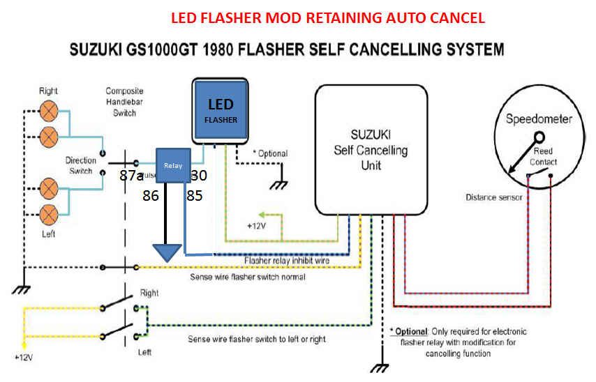
The shunt simply loads the circuit in the same fashion as do the original incandescent bulbs, such that the flasher is able to function. Other ways to accomplish flashing of light loads such as LEDs which I recall using:
1) Aftermarket flasher units are made expressly for LED and other light loads.
2) Connecting the flasher to ground by way of a resistor or diode string to cause the flasher to operate and using a normally closed relay shunted across the flasher. Causes the LEDs to flash in reverse to the flasher but is reliable. The third/indicator terminal of some flashers works well for this purpose.
3) Use of a flasher bulb to control the relay coil as these are both available in lower voltages which can be combined with a resistor. I used one from a flash light to make the warning light on a boat house flash when the temperature dropped too low.

Lots of ways to do this. Someone suggested using an electronic timer/flasher from Mouser or one of those suppiers for this purpose on one of the KLR groups. I like to use a simple relay combination although the electronics gurus will often cob together a circuit. Personally, I think they only do it to make we dinosaurs feel even more inferior but if that's the reason, it works.:oops:

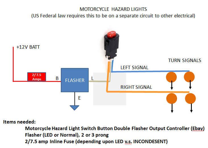
On another, related, subject, has anyone bridged the R&L signal light leads in order to achieve 4-way flashers? I always get around to this modification but am a bit concerned about doubling the signal light load into that controller.

As everyone will know, there are two common means of achieving 4-way flasher operation. The most simple is to connect a switch between the right & left signal bulb leads. Activate the turn signals in either direction and close the switch so that both side turn signals are powered from the side which is activated. Simple and works efficiently. I use it frequently on my ST1100 when moving slowly in traffic as in a construction zone.

Another means is that which is used by automobile manufacturers who wish to make the 4-ways active when the ignition is off. They often have a much more complex signal switch which allows the brake lights and rear signals to share the same bulb filaments. In even the simpler systems which use separate brake and turn indicators, the 4-way system is powered separately through its own switch and flasher. I don't bother with that system on a bike because, IMO, the battery capacity is insufficient to allow the 4-ways to endure. If one wished to have a 4-way system which could operated for 1/2 hour or longer, sufficient time to repair a tire for example, LED's or HID strobes would need to be considered. I have an LED light bar transversely mounted under the luggage rack on the top of my ST1100's Givi trunk which uses a two wire flat connector to connect to the bike's harness. This allows the LED bar to be connected to the always powered battery charging plug stored behind the rear side cover. The same plug is also power for pillion heated vesta as this will not remain connected to drain the battery.

An acquaintance connected a relay to flash the opposite side signals but managed to wire it so that the lights alternated side to side. He received official attention almost the first time used,:D and brought it by for help. I proposed that we simply install one red and one blue lenses onto his front signals but he was not amused.;)

I'm not a fan of LED's as turn signals, indicators or brake lights unless their performance is at least equal to incandescent which is seldom the case. The practical issue is that the lighting enclosures and lenses are a problem. There are many excellent purpose designed LED lights on the market but few original lighting units perform well with an LED.
I think the answer is usually to replace the complete light but that is an issue with a collector bike.
 
Are you sure it's "Cancel"? :-k

It might be "Control". :o

I looked into the matter briefly (all my signals are still working fine, so there wasn't much incentive) some time ago, and found that if the turn signals are flashing, grounding the "C" wire would stop them. I also tried to get a good reading on the status of the "C" wire (dark blue, I think) while the signals were flashing, but connecting a meter must have been enough of a "ground" to cancel the system. Or, it might have been enough of a drain to remove a very small amount of "high" signal that was turning the flasher unit ON.

I have come to the conclusion that there must be a small electronic relay built in to the flasher unit that is turned on by the "C" wire (which comes from the control unit) and allows the current to flow from the orange/green wire, through the flasher unit and come out as intermittent current on the light blue wire, which is then fed to the turn signal switch, which determines which side it will go to. Since nothing moves physically to stop the current flow, I think it's inside the flasher unit, which is why you can not get one off the shelf at any parts store to replace it.

I was hoping to be able to do something like your first diagram, but probably have the relay in the power side of the LED flasher, rather than the load (flashing) side, but was not able to determine whether that signal wire would be able to activate a relay.

If you are able to come up with a "Solid State Self-Cancelling LED Flasher" box (and keep the cost reasonable), I will get a few from you.
icon_thumbsup.gif


.

Yea not really sure if control or cancel; I was reading Andre's write up.

So as best you can tell the C line needs to be at ground to stop flashing? Well it doesn't matter the relay could be rearranged for that. Put one side of the coil on O/G and let the control box short it.

You are correct the relay could probably be put on either side. Not really sure which is better other than what the flasher will do when you keep pulling power from it.

I will have to get my scope out tommorow and measure it. Those at 10M ohm probes I think should be high enough impedance to solve the mystery. Either than or a current clamp.

At this point I'm after bigger fish but if I do some prototypes and have some PCB space I might knock out a few PCB's to accommodate. If this relay with flasher works it might just be to support that.
 
Last edited:
I did a bench test, on the three prong relay conencted to two turn signal in parallel using a +12V supply. When I leave C open the flasher runs two lights but not one (as expected). When I ground the C terminal is clatters. When I applied +12V to the C terminal the flasher stops in the off position. So +12V means CANCEL.

When I get my LED flasher I will see if it is plug and play or if the external; relay is required.

I did not bother to figure out the mechanization, but here is another thread from some guys adding in a FET to short out the capacitor in theirs. It makes sense that if the voltage across a capacitor is what energizes a coil to close the contacts that shorting it would prevent further flashing. Matters not as I'll be using a solid state LED flasher .

http://xjbikes.com/Forums/viewtopic/t=13520.html
 
Last edited:

Thanks Dale,

I had PMed Andre and he PMed those back as well. I think I basically understand the issues. I'm looking at some other alternatives as I really hate to open up a sealed relay unit.

I'm pretty sure that there is a simple solution to modify the harness in one place and then you can mix and match aftermarket relays and OEM turn control units.

More later.

It is later

http://www.thegsresources.com/_forum/showthread.php?t=218717
 
Last edited:
Jim,
When I played around a while ago I also made up a separate interface unit, but scrapped that idea as another little black box would start complicating matters. Basically the only thing to watch is the output from the cancelling unit. You do not want to damage a part that is hard to get to! It also did not operate a 12V relay so I used a 5V with a series and a parallel protection diode, for reversed connection and back EMF protection.

My reasoning for modifying the flasher relay is that the OEM flasher relay is already a custom made one and only works on the 5 position switch type turn signals, so to make an aftermarket drop-in seemed to me a good idea at the time.


Just another note the OEM flasher relay works in reverse to others, it is normally on and the lights go off when the relay operates. This allows for the cancelling function by keeping the relay operated through its 2nd 100 ohm holding coil and the lights then stay off while the relay is operated!
The switch position when normal does not connect battery to the relay and the lights are then off although the contact in the flasher relay is normally closed.

Hope this helps
 
I'll just add that I modified my turn signal system to use an LED flasher along WITH the stock self cancelling unit. The LED flasher provides the signal to the bulbs and a solid state relay / micro controller listens for the off-signal from the self canceller. I put the whole thing into a single 3d printed enclosure with prongs to plug into the stock wiring. All completely reversable and non-destructive.

It's been working flawlessly for a long time now. Also, because the relay is also a microcontroller, I can adjust the amount of time after the self cancel turns off to actually cancel the signal. IE.. Extend it. I always felt like it was too short.

And lastly, I think the relay itself might be able to act as the flasher as it has all sort of functions.
 
Back
Top