Required reading for all forum users!!!
Welcome!
Register to access the full functionality of the GSResources forum. Until you register and activate your account you will not have full forum access, nor will you be able to post or reply to messages.
A note to new registrants...
All new forum registrations must be activated via email before you have full access to the forum.
A Special Note about Email accounts!
DO NOT SIGN UP USING hotmail, outlook, gmx, sbcglobal, att, bellsouth or email.com. They delete our forum signup emails.
A note to old forum members...
I receive numerous requests from people who can no longer log in because their accounts were deleted. As mentioned in the forum FAQ, user accounts are deleted if you haven't logged in for the past 6 months. If you can't log in, then create a new forum account. If you don't get an error message, then check your email account for an activation message. If you get a message stating that the email address is already in use, then your account still exists so follow the instructions in the forum FAQ for resetting your password.
Have you forgotten your password or have a new email address? Then read the forum FAQ for details on how to reset it.
Any email requests for "can't log in anymore" problems or "lost my password" problems will be deleted. Read the forum FAQ and follow the instructions there - that's what we have one for...


")


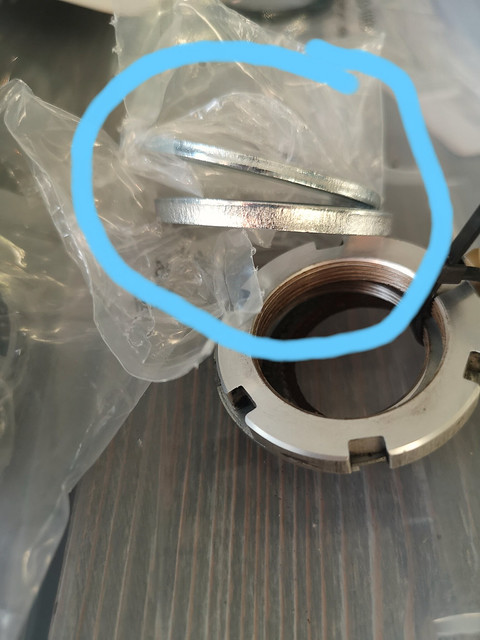
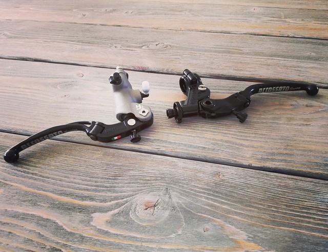
") I found this in an old post from 2006, so it's strange that my kit didn't include instructions. Maybe they're online somewhere.
I found this in an old post from 2006, so it's strange that my kit didn't include instructions. Maybe they're online somewhere.


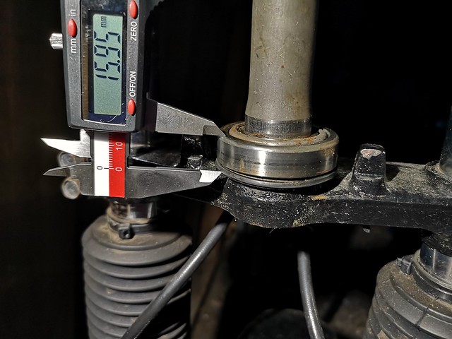


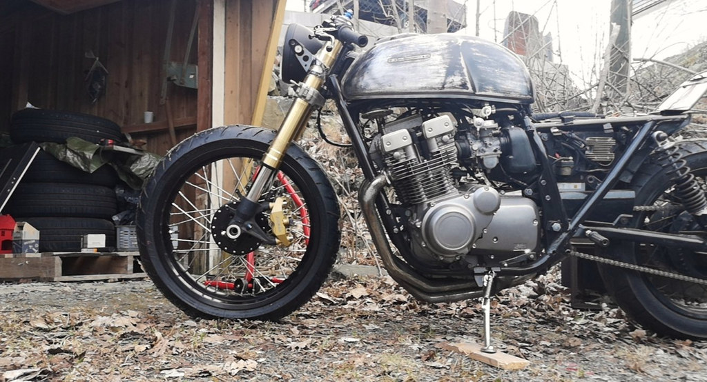
 ). It seems the fender will touch the lower clamp just before the tyre hits the exhaust. I need to set compression and preload so this doesn't happen, but I don't think it'll be a problem. I'll also hook up a GoPro for the first few rides to see how the fork behaves.